Glow plug energization control apparatus and method

a technology of glow plugs and control apparatuses, which is applied in the direction of electric control, lighting and heating apparatus, machines/engines, etc., can solve the problems of unburned gas emissions, unstable engine revolution, and deterioration of durability of resistance heaters, so as to prevent engine rough idling and avoid misfires. , the effect of preventing engine rough idling

Inactive Publication Date: 2007-10-04
NGK SPARK PLUG CO LTD
View PDF1 Cites 9 Cited by
  • Summary
  • Abstract
  • Description
  • Claims
  • Application Information

AI Technical Summary

Benefits of technology

[0008]It is conceivable to maintain the resistance heater temperature at a higher level in order to assist ignition, avoid misfire and prevent engine rough idling. The resistance heater however deteriorates in durability when the resistance heater temperature is maintained at such a higher level.
[0009]It is therefore an object of the present invention to provide an apparatus and method for controlling the energization of a glow plug disposed in an internal combustion engine so as to shorten unstable engine revolution time after the engine start while securing durability for the glow plug (resistance heater).

Problems solved by technology

In the case where the engine starts by cranking under low-temperature conditions, there is a possibility that rough idling may occur for a long time to cause large engine vibration and unstable engine revolution due to the occurrence of misfire in a cylinder or cylinders of the engine.
This results in driver's discomfort and unburned gas emissions.
The resistance heater however deteriorates in durability when the resistance heater temperature is maintained at such a higher level.

Method used


Image

  • Glow plug energization control apparatus and method
  • Glow plug energization control apparatus and method
  • Glow plug energization control apparatus and method

Examples


Embodiment Construction

[0027]The present invention will be described in detail below with reference to the drawings.

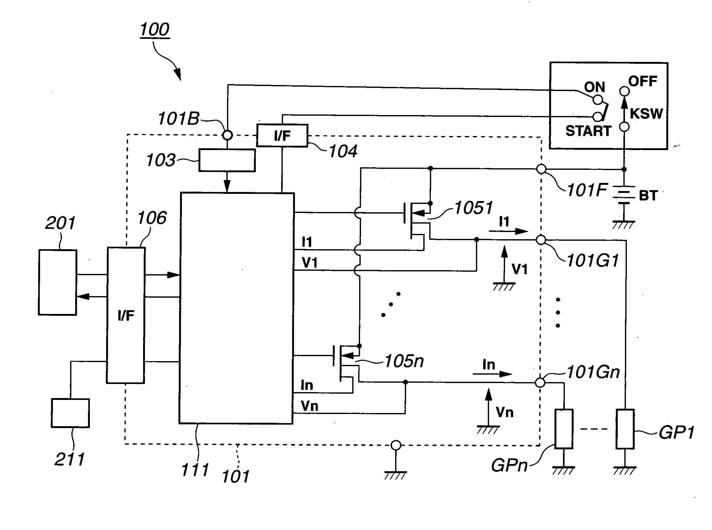
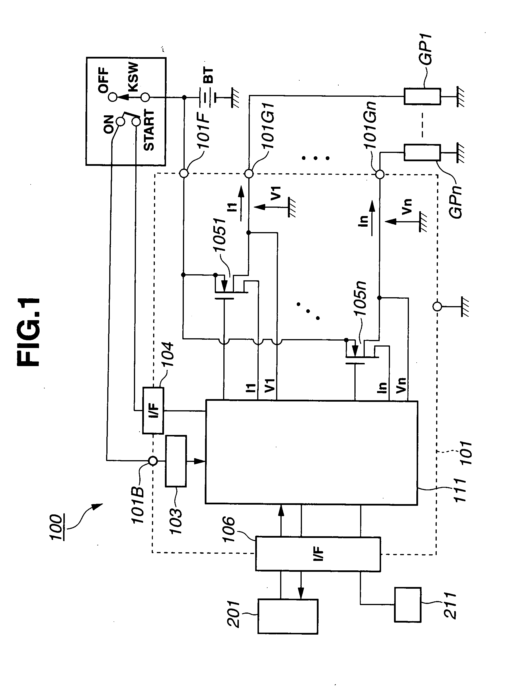
[0028]The following exemplary embodiment of the present invention refers to a glow plug energization control system 100 for controlling the energization of n number of glow plugs GP (GP1 to GPn) in an internal combustion diesel engine.

[0029]The structures of the glow plugs GP (GP1 to GPn) will be first explained blow.

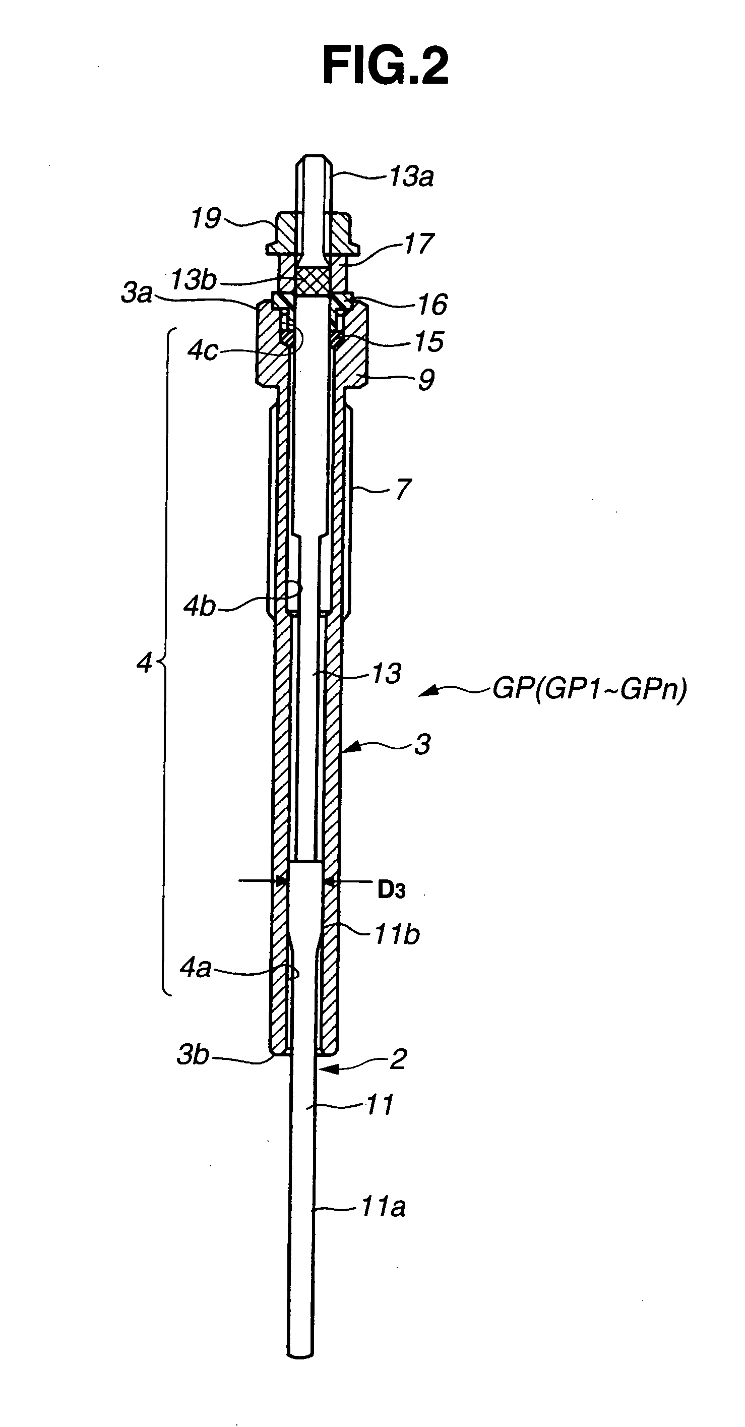
[0030]As shown in FIGS. 2 and 3, each of the glow plugs GP is provided with a sheath heater 2 as a resistance heater, a cylindrical metal shell 3, a terminal rod 13, an O ring 15, an insulating bushing ring 16, a push ring 17 and a nut 19.

[0031]The sheath heater 2 includes a sheath tube 11 formed with a closed front end, a plurality of resistance coils: a heating coil 21 and a control coil 23 connected in series and an insulating material 27. The sheath tube 11 has a front cylindrical portion 11a and a rear cylindrical portion 11b larger in diameter than the front cylindrical po...


PUM


Abstract

There is provided an energization control apparatus for a glow plug in an engine, including a post-start glow section to control energization of a resistance heater of the glow plug by a battery after start of the engine. The post-start glow section is configured to evaluate revolution stability of the engine and control the energization of the resistance heater according to a first control pattern when the engine revolution stability is higher than or equal to a threshold level and according to a second control pattern that achieves a higher temperature of the sheath heater than the first control pattern when the engine revolution stability is lower than the threshold level.

Description

BACKGROUND OF THE INVENTION[0001]The present invention relates to an apparatus and method for controlling the energization of a glow plug disposed in an internal combustion engine.[0002]Hereinafter, the term “front” refers to a heating end side with respect to the axial direction of a glow plug, and the term “rear” refers to a side opposite the front side.[0003]Glow plugs are generally equipped with resistance heaters and mounted on diesel engines to aid engine starting. Various energization control techniques have been proposed for the glow plugs.[0004]Japanese Laid-Open Patent Publication No. 56-129763 and No. 60-67775 propose one type of glow plug energization control technique in which the energization control includes two control phases: “pre-glow” and “after-glow”. The pre-glow phase is performed upon actuation of a key switch to supply a large amount of power to the glow plug and raise the temperature of the resistance heater to a first target temperature rapidly during sever...

Claims


Application Information

Patent Timeline
Patent Type & Authority Applications(United States)
IPC IPC(8): F23Q7/00
CPCF02D41/1498F02P19/025F02P19/022F02P19/021
Inventor GOTOU, SHUNSUKEONO, HIROSHIOOTUBO, MASANORI
Owner NGK SPARK PLUG CO LTD
Why Eureka
Try Eureka