Hydraulic control device for automatic transmission

Active Publication Date: 2005-03-24
JATCO LTD
View PDF3 Cites 9 Cited by
  • Summary
  • Abstract
  • Description
  • Claims
  • Application Information

AI Technical Summary

Benefits of technology

[0014] The present invention has been made in view of the aforementioned problem, and it is therefore an object of the present invention to provide a hydraulic control devic

Problems solved by technology

Since the oil pressure switch and peripheral hydraulic circuits thereof are configured to have a high responsiveness, the dire

Method used


Image

  • Hydraulic control device for automatic transmission
  • Hydraulic control device for automatic transmission
  • Hydraulic control device for automatic transmission

Examples


Embodiment Construction

[0036] A preferred embodiment of the present invention will be described hereinbelow.

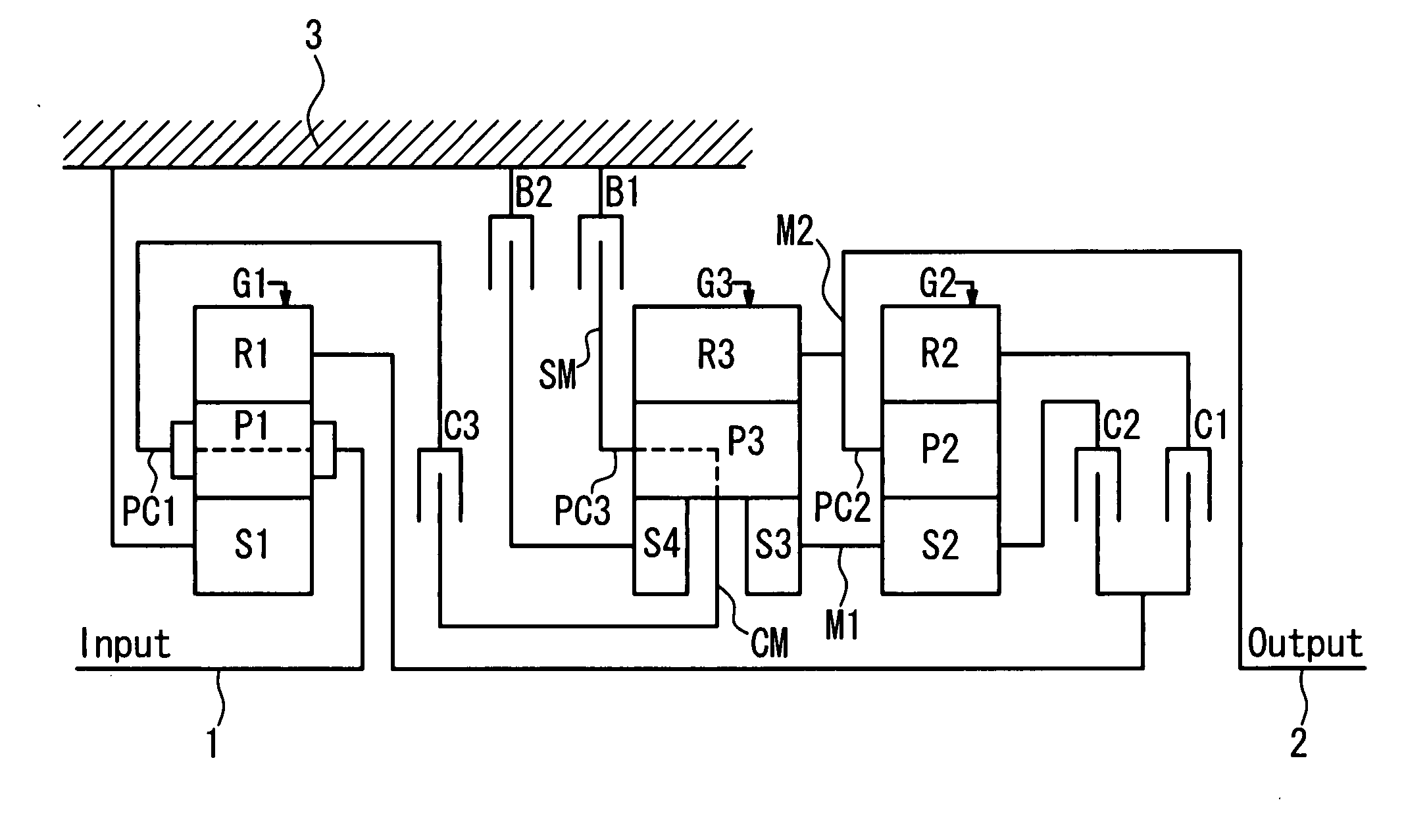
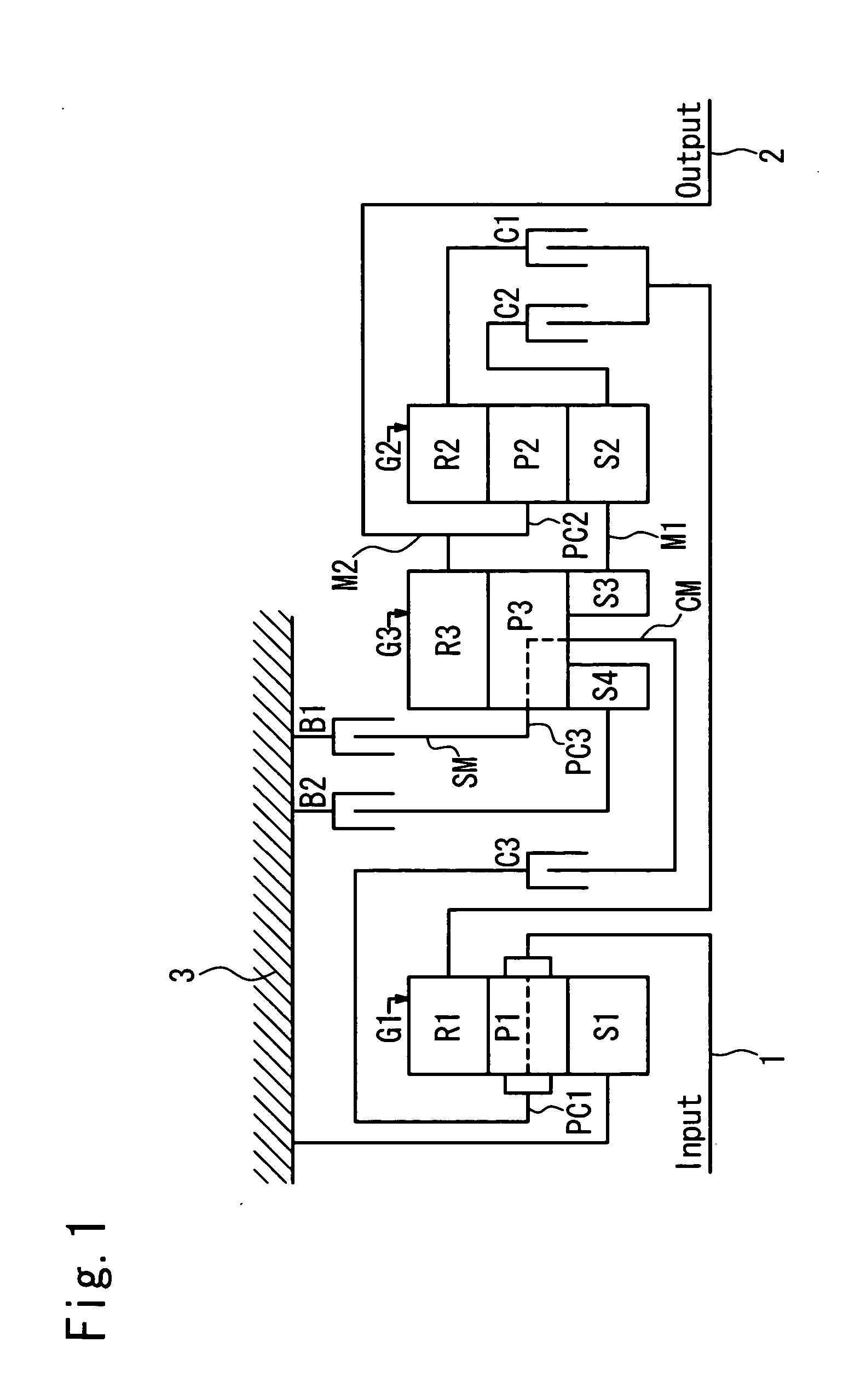
[0037]FIG. 1 schematically shows an automatic transmission in this embodiment.

[0038] In the automatic transmission (speed reduction double pinion type), a first planetary gear set G1 comprised of a single pinion type planetary gear set and served as a reduction gear, a third planetary gear set G3 of a double sun gear type and a second planetary gear set G2 of a single pinion type are coaxially arranged in these order from a side close to an input shaft 1 (Input). The first planetary gear set G1 constitutes a speed reduction planetary gear set, and the second planetary gear set G2 and the third planetary gear set G3 constitute a speed change planetary gear set (occasionally referred to as Ishimaru-type planetary gear train hereinafter).

[0039] The first planetary gear set G1 is comprised of a single pinion type planetary gear set having a first sun gear S1, a first ring gear R1 and a first carrier ...


PUM


Abstract

A hydraulic control device for an automatic transmission comprises an engagement element pressure control section for controlling an engagement element pressure, engagement elements supplied with the engagement element pressure, and an oil pressure switches provided in oil supply paths of the engagement element pressure. The plural gear positions are achieved by engaging or disengaging the engagement elements. The engagement element pressure control section controls the engagement element pressure with a first gain when the engagement elements are in the shifting state and controls the engagement element pressure with a second gain when the engagement elements are in the engagement state.

Description

BACKGROUND OF THE INVENTION [0001] 1. Field of the Invention [0002] The present invention relates to a hydraulic control device for an automatic transmission. [0003] 2. Description of the Prior Art [0004] An automatic transmission has a transmission mechanism that is comprised of rotational elements such as planetary gear sets and engagement elements such as clutches and brakes that engage and disengage the rotational elements. The engagement elements are respectively actuated by oil pressure, and a plurality of gear positions are obtained by engaging and disengaging the engagement elements in predetermined combinations. [0005]FIG. 13 shows a hydraulic circuit of an oil pressure that is supplied to the engagement elements. [0006] The hydraulic circuit generating an engagement element pressure Pc that is supplied to an engagement element 60 is constituted by a regulating valve 62 for regulating a line pressure generated by a not-shown oil pump by means of pressure reduction control a...

Claims


Application Information

Patent Timeline
IPC IPC(8): F16H3/66F16H59/68F16H61/00F16H61/02F16H61/68F16H61/682F16H61/686
CPCF16H3/663F16H61/0021F16H61/0204F16H61/0251F16H61/12F16H2059/683F16H2200/0052F16H2200/201F16H2200/2097F16H2306/50F16H61/686
Inventor KAIZU, KENICHIYAMAMOTO, HIDEHARU
Owner JATCO LTD
Why Eureka
Try Eureka