Drive circuit and method for inverters of wind energy installations

a technology of driving circuit and wind energy installation, which is applied in the direction of electric generator control, dynamo-electric converter control, greenhouse gas reduction, etc., can solve the problems of affecting the life of switching elements, switching elements which are in each case switched on, and are subject to an increased thermal load, so as to reduce the thermal load on them, avoid switching losses, and reduce the effect of switching losses

Active Publication Date: 2009-12-31
SIEMENS GAMESA RENEWABLE ENERGY SERVICE GMBH
View PDF10 Cites 15 Cited by
  • Summary
  • Abstract
  • Description
  • Claims
  • Application Information

AI Technical Summary

Benefits of technology

[0008]In the simplest case, this is done by definition of the absolute potentials of the inverter such that an extreme phase potential (for example the lowest phase potential) is identical to a potential in the intermediate circuit (for example its ground potential). For the other half-cycle, a shift value is calculated such that the opposite extreme phase potential (for example the highest) is identical to the other potential in the intermediate circuit (for example its upper potential). This shifting means that one extreme phase (that with the highest potential) corresponds to the upper intermediate-circuit voltage; the corresponding switching element of the inverter can thus be switched on and need no longer be clocked. The switching losses which occur as a result of clocking and lead to heating of the switching element are thus avoided. The shift is in the opposite direction during the subsequent half-cycle, and the lowest phase potential corresponds to the lower intermediate-circuit voltage (for example ground), as a result of which the corresponding switching element of the inverter can once again be switched on completely, and need no longer be clocked. Thus, seen over one cycle, the switching element for the highest phase potential and that for the lowest phase potential each need not be clocked for one half-cycle, that is to say for half of the cycle duration, thus correspondingly halving the switching losses.
[0009]However, this does not yet provide any improvement for the switching elements for the middle phase potential. In order to additionally reduce the thermal load on them as well, the invention makes use of a trick, by applying an additional voltage. This is chosen such that it reduces the potential of the middle phase in one of the two half-cycles down to the lower intermediate-circuit potential (or raises it to the upper intermediate-circuit potential), as a result of which the corresponding switching element likewise no longer need be clocked; for compensation, the additional voltage is correspondingly added in the other half-cycle (or reduced), in such a way that it is cancelled out over one complete cycle and therefore has virtually no effect on the generator. The invention therefore makes use of this trick to ensure that, when there are three phases, the lowest, the highest and the middle phase, the time for which clocked operation of the switching elements for the inverter is switched on is halved. The switching losses of the inverter are therefore halved. Since, in the practical embodiment of the converters, the switching losses in general dominate at least in the region of the synchronization point over the switched-on losses of the switching elements, the reduction in the switching losses according to the invention significantly affects the thermal load on the switching elements. As a result of the reduced thermal load, the current flow can in contrast be increased. The switching technique according to the invention therefore allows more torque to be transmitted even in the region of the synchronization point. The invention achieves this virtually solely by the special drive for the switching elements and the negligible additional hardware complexity for obtaining the additional voltage, and thus in a surprisingly simple manner achieves a considerable increase in the current load capacity of the converter at the synchronization point.

Problems solved by technology

It has been found that operation in the region of the synchronous rotation speed (synchronization point) results in problems.
As a result of the low frequencies, phases with a severe thermal load and phases with a light thermal load no longer alternate sufficiently quickly, as a result of which the switching elements which are in each case switched on, in particular, are subject to an increased thermal load.
This adversely affects the life of the switching elements, and can lead to them failing.
However, from the mechanical point of view, a reduction in the maximum permissible current actually means that the maximum permissible torque acting on the wind rotor is limited to a correspondingly greater extent.
In consequence, the controllable rotation-speed range around the synchronization point is restricted by the more greatly limited, that is to say reduced, torque.
This is sufficient for driving motors, but, in the case of variable rotation-speed wind energy installations, can lead to the pulse repetition frequency of the relevant switching elements falling excessively during operation in the region of the synchronous rotation speed and therefore still increasing the thermal load, particularly on the switching elements for this phase.
In fact, this known power converter is therefore not actually suitable for use with variable rotation-speed wind energy installations.

Method used


Image

  • Drive circuit and method for inverters of wind energy installations
  • Drive circuit and method for inverters of wind energy installations
  • Drive circuit and method for inverters of wind energy installations

Examples


Embodiment Construction

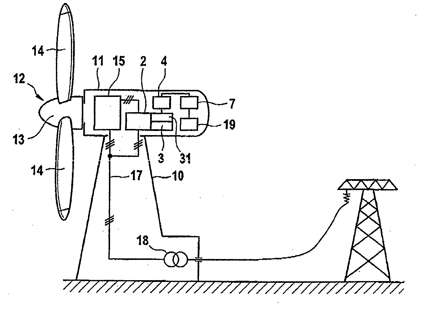
[0024]FIG. 1 illustrates one exemplary embodiment of a wind energy installation according to the invention. This comprises a tower 10 on which a pod 11 is mounted and can pivot in the azimuth direction. A wind rotor 12 is arranged such that it can rotate on one end face of the pod 11. This wind rotor 12 comprises a hub 13 with one or more rotor blades 14, and drives a generator 15 via a rotor shaft (which is not illustrated). This generator 15 converts the mechanical power produced by the wind rotor 12 from the wind to electrical power. The generator 15 is a double-fed asynchronous machine, although other generator types may also be provided, in particular synchronous machines. A converter 2 is connected to the generator 15. A line 17 is connected to the generator 15 and to the converter 2 and it trans-ports the electrical power that is produced through the tower 10 to a medium-voltage transformer 18, which is arranged at the foot of the tower 10, in order to be passed on to a netwo...


PUM


Abstract

A converter for a wind energy installation and a method. The converter includes an inverter which drives a generator via a plurality of phases and an intermediate circuit having an intermediate-circuit voltage between an upper and a lower intermediate-circuit potential. The generator is driven with phase potentials at a variable frequency. A shift value is calculated between an extreme phase potential and one of the intermediate-circuit potentials, a separation value is determined between a middle phase potential and the closest intermediate-circuit potential, and an additional voltage is generated using the separation value as amplitude. The phase potentials are shifted through the shift value and the additional voltage is added to the middle phase potential. Accordingly, the switching elements in the converter do not need to be clocked in every second half-cycle resulting in reduced switching losses and increased current load capacity of the converter.

Description

REFERENCE TO RELATED APPLICATIONS[0001]This application claims the priority of German Patent Application No. 10 2008 028 809.8, filed Jun. 19, 2008, the contents of which are incorporated herein by reference.FIELD OF THE INVENTION[0002]The invention relates to a drive circuit for converters of wind energy installations comprising an inverter which has a plurality of phases for connection of a generator, in particular a double-fed asynchronous generator, and an intermediate circuit which is connected to the inverter. The invention also relates to a method for operation of a converter having a drive circuit such as this, and to a wind energy installation equipped with it.BACKGROUND OF THE INVENTION[0003]Modern wind energy installations are designed for variable rotation speeds. This means that the wind rotor revolves at a rotation speed which is governed by the load, and that the generator produces electrical power at a correspondingly variable frequency. In order to allow this variab...

Claims


Application Information

Patent Timeline
Patent Type & Authority Applications(United States)
IPC IPC(8): H02P9/04H02M7/538
CPCF03D7/0272F03D9/021F05B2270/502Y02E10/76H02M7/53875Y02E10/723F05B2270/504F03D9/11F03D9/255Y02E10/72Y02E70/30
Inventor LETAS, HEINZ-HERMANN
Owner SIEMENS GAMESA RENEWABLE ENERGY SERVICE GMBH
Why Eureka
Try Eureka