Dynamic brake circuit assembly for a wind turbine

a technology of brake circuit and wind turbine, which is applied in the direction of machines/engines, passive/reactive control, electric generator control, etc., can solve the problems of voltage overshoots on the dc bus voltage in the power converter, and the disturbance of the dc bus voltage, so as to achieve the damage of the converter components

Active Publication Date: 2020-04-07
GENERAL ELECTRIC CO
View PDF57 Cites 0 Cited by
  • Summary
  • Abstract
  • Description
  • Claims
  • Application Information

AI Technical Summary

Benefits of technology

[0017]In yet another aspect, the present disclosure is directed to a method for controlling peak voltage of a DC link of a power converter of an electrical power system connected to a power grid with minimal switching losses. The method includes electrically coupling a dynamic brake assembly to a DC link of the power converter. The dynamic brake includes a plurality of switching devices connected in parallel and a plurality of inductors electrically coupled between the plurality of switching devices. The method also includes receiving a voltage measurement of the DC link of the power converter. Further, the method includes comparing the voltage measurement of the DC link to a voltage threshold. When the voltage measurement is at or above the voltage threshold, the method includes turning on the dynamic brake assembly of the power converter such that the at least one inductor receives at least part of a load generated by the power converter.

Problems solved by technology

As the length of the transmission line feeder to the DFIG wind turbine is increased, however, response to grid transients and grid disturbances causes oscillations of power into and out of the power converter, which can create disturbances on the DC bus voltage therein.
As longer transmission line length is typically desired (and possibly coupled with larger grid voltage transients), the voltage overshoots on the DC bus voltage in the power converter may reach a level that damages the converter components.

Method used


Image

  • Dynamic brake circuit assembly for a wind turbine
  • Dynamic brake circuit assembly for a wind turbine
  • Dynamic brake circuit assembly for a wind turbine

Examples


Embodiment Construction

[0036]Reference now will be made in detail to embodiments of the invention, one or more examples of which are illustrated in the drawings. Each example is provided by way of explanation of the invention, not limitation of the invention. In fact, it will be apparent to those skilled in the art that various modifications and variations can be made in the present invention without departing from the scope or spirit of the invention. For instance, features illustrated or described as part of one embodiment can be used with another embodiment to yield a still further embodiment. Thus, it is intended that the present invention covers such modifications and variations as come within the scope of the appended claims and their equivalents.

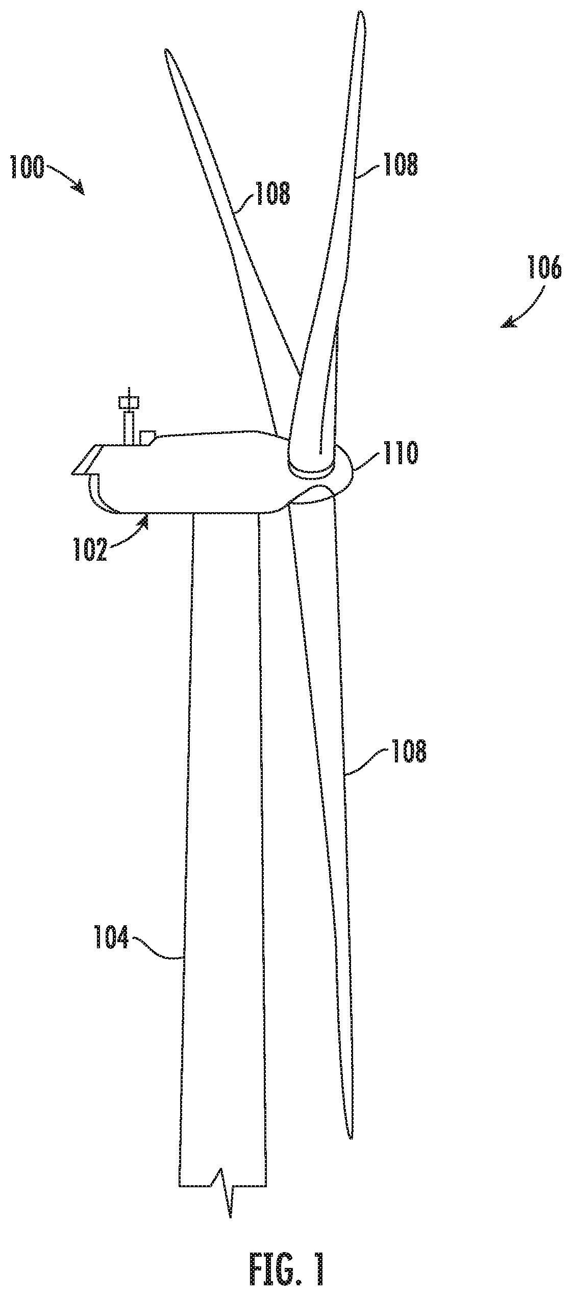
[0037]Referring now to the drawings, FIG. 1 illustrates a perspective view of a portion of one embodiment of a wind turbine 100 according to the present disclosure that is configured to implement the method as described herein. As shown, the wind turbine 10...


PUM


Abstract

A power converter assembly for an electrical power system connected to a power grid includes a rotor-side converter configured for coupling to a generator rotor of a generator of the electrical power system, a line-side converter electrically coupled to rotor-side converter via a DC link, and a dynamic brake assembly electrically coupled to the DC link. The line-side converter is configured for coupling to the power grid. The dynamic brake assembly includes a plurality of switching devices connected in parallel and a plurality of inductors electrically coupled between the plurality of switching devices.

Description

FIELD[0001]The present disclosure relates generally to wind turbines and, more particularly, to improved dynamic brake circuit assemblies for wind turbines.BACKGROUND[0002]Wind power is considered one of the cleanest, most environmentally friendly energy sources presently available, and wind turbines have gained increased attention in this regard. A modern wind turbine typically includes a tower, generator, gearbox, nacelle, and one or more rotor blades. The rotor blades capture kinetic energy of wind using known airfoil principles. For example, rotor blades typically have the cross-sectional profile of an airfoil such that, during operation, air flows over the blade producing a pressure difference between the sides. Consequently, a lift force, which is directed from a pressure side towards a suction side, acts on the blade. The lift force generates torque on the main rotor shaft, which is geared to a generator for producing electricity.[0003]During operation, wind impacts the rotor...

Claims


Application Information

Patent Timeline
Patent Type & Authority Patents(United States)
IPC IPC(8): H02P9/08H02P9/00H02P9/30F03D9/00F03D17/00F03D9/25F03D7/02F03D1/00H02M1/36H02M5/458H02P101/15
CPCF03D9/255F03D7/0244F03D1/00H02P9/08H02M1/36H02P9/305H02P9/007H02M5/4585F03D17/00H02P2101/15F05B2270/602F05B2220/30F05B2270/337F05B2220/70646F05B2260/903F05B2270/402F05B2270/1011F05B2270/502H02M3/155H02M5/42H02P9/105H02P29/0241H02M1/327H02M1/346Y02B70/10Y02E10/72Y02E10/76
Inventor WAGONER, ROBERT GREGORYHOLLIDAY, CORNELIUS EDWARDNIEMOELLER, BENJAMIN ARTHURSMITH, DAVID
Owner GENERAL ELECTRIC CO
Why Eureka
Try Eureka