Sealed type heat exchanging system of battery pack

a battery pack and heat exchange technology, applied in secondary cell servicing/maintenance, cell components, electrochemical generators, etc., can solve the problems of large amount of heat generated by unit cells, degraded unit cells, and air pollution, and achieve the effect of removing heat from the battery pack, easy control of the optimum operating and increasing the temperature of the battery pack

Active Publication Date: 2007-10-25
LG ENERGY SOLUTION LTD
View PDF4 Cites 28 Cited by
  • Summary
  • Abstract
  • Description
  • Claims
  • Application Information

AI Technical Summary

Benefits of technology

[0011] As a result of a variety of extensive and intensive studies and experiments to solve the problems as described above, the inventors of the present invention have developed a heat exchange system that is capable of circulating a coolant for cooling a battery pack therein by a heat exchange unit without introduction of the coolant from the outside of the heat exchange system, and found that the developed heat exchange system has the effect of accomplishing the reduction in size of a battery system, reducing influences caused by external conditions, decreasing noise, and effectively controlling the optimum operating temperature of the battery pack.
[0014] In the present invention, the “heat exchange medium” is a medium that is free to flow in the heat exchange system and can easily control the optimum operating temperature of the battery pack. Preferably, the heat exchange medium is air.
[0015] When the temperature of the battery pack is higher than the optimum operating temperature, the heat exchange medium absorbs heat generated from the battery pack and transmits the absorbed heat to the heat exchange unit, thereby removing the heat from the battery pack. When the temperature of the battery pack is lower than the optimum operating temperature, on the other hand, the heat exchange medium absorbs heat generated from the heat exchange unit and transmits the absorbed heat to the battery pack, thereby increasing the temperature of the battery pack. In this way, the optimum operating temperature of the battery pack is controlled.
[0019] When the measured temperature of the battery pack is higher than the optimum operating temperature level, electric current is supplied to the heat control member such that an endothermic reaction occurs at the end of the heat control member adjacent to the inner heat exchange member, and an exothermic reaction occurs at the end of the heat control member adjacent to the outer heat exchange member. As a result, heat is discharged out of the battery system. When the measured temperature of the battery pack is lower than the optimum operating temperature level, on the other hand, electric current is supplied to the heat control member such that an exothermic reaction occurs at the end of the heat control member adjacent to the inner heat exchange member, and an endothermic reaction occurs at the end of the heat control member adjacent to the outer heat exchange member. As a result, the interior temperature of the battery system is increased.

Problems solved by technology

One of the biggest problems caused from vehicles using fossil fuel, such as gasoline and diesel oil, is creation of air pollution.
In such a high-output, large-capacity secondary battery, however, a large amount of heat is generated from the unit cells during the charge and the discharge of the unit cells.
When the heat generated from the unit cells during the charge and the discharge of the unit cells is not effectively removed, heat is accumulated in the unit cells with the result that the unit cells are degraded.
However, the cooling system with the above-described construction has several problems.
First, the air used as the coolant is supplied from the outside of vehicle with the result that the air is considerably affected by external conditions, such as humidity and temperature.
As a result, the size of the cooling system is increased.
Second, when, in spite of removal of foreign matter by filtering the coolant, some of the foreign matter is introduced through the inlet port and the outlet port, and is brought into contact with unit cells of a battery pack, the outer surfaces of the unit cells may be physically or chemically damaged.
In addition, noise and vibration generated due to the operation of a coolant introduction device, such as a fan or a pump, may be transmitted to a passenger(s) through the inlet port and the outlet port.
Nevertheless, a large amount of heat cannot be effectively removed by the structures disclosed in the publications.
As a result, the structures disclosed in the publications are not suitable for vehicles using a large-sized battery pack, such as electric vehicles (EV) and hybrid electric vehicles (HEV).
In addition, when the unit cells of the battery pack have low temperature, battery components may be damaged.
Furthermore, the degradation of the battery components may be accelerated due to the abrupt increase of the temperature of the air introduced into the battery pack.

Method used


Image

  • Sealed type heat exchanging system of battery pack
  • Sealed type heat exchanging system of battery pack
  • Sealed type heat exchanging system of battery pack

Examples


Embodiment Construction

[0029] Now, a preferred embodiment of the present invention will be described in detail with reference to the accompanying drawings. It should be noted, however, that the scope of the present invention is not limited by the illustrated embodiment.

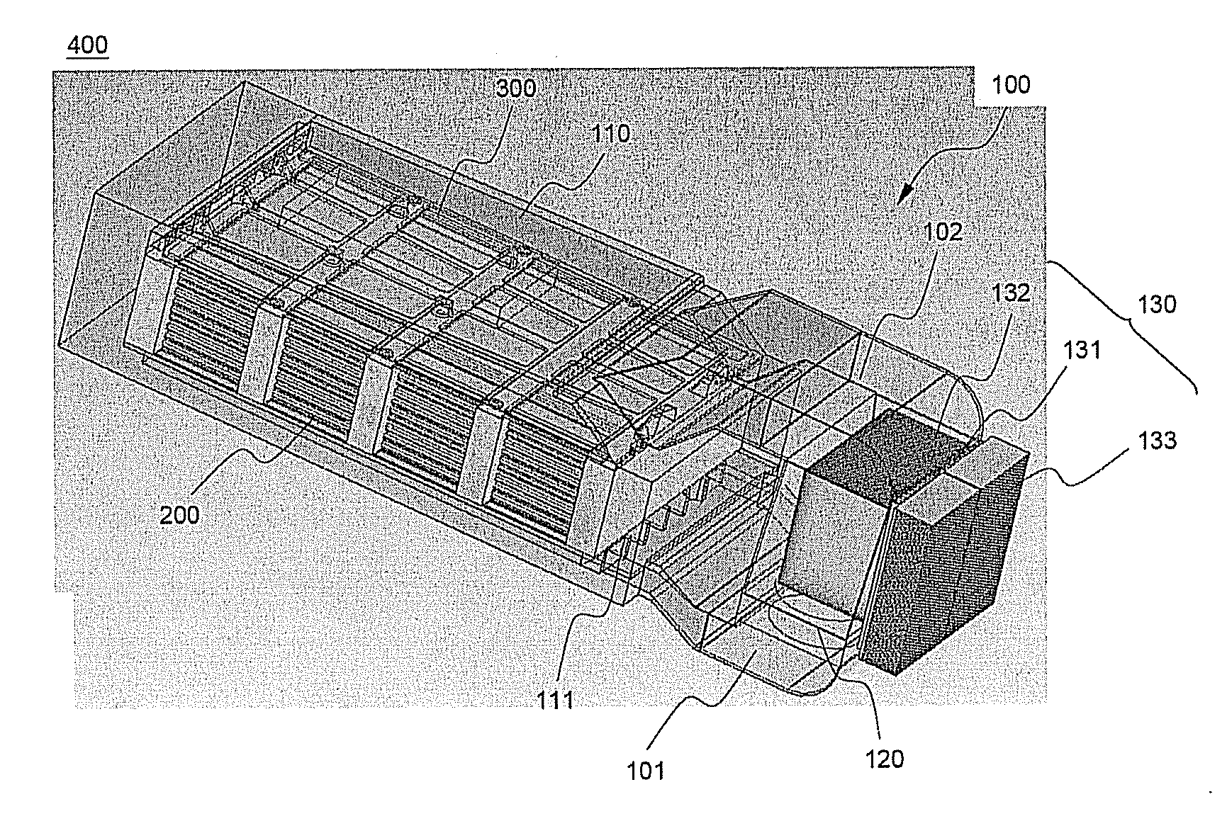
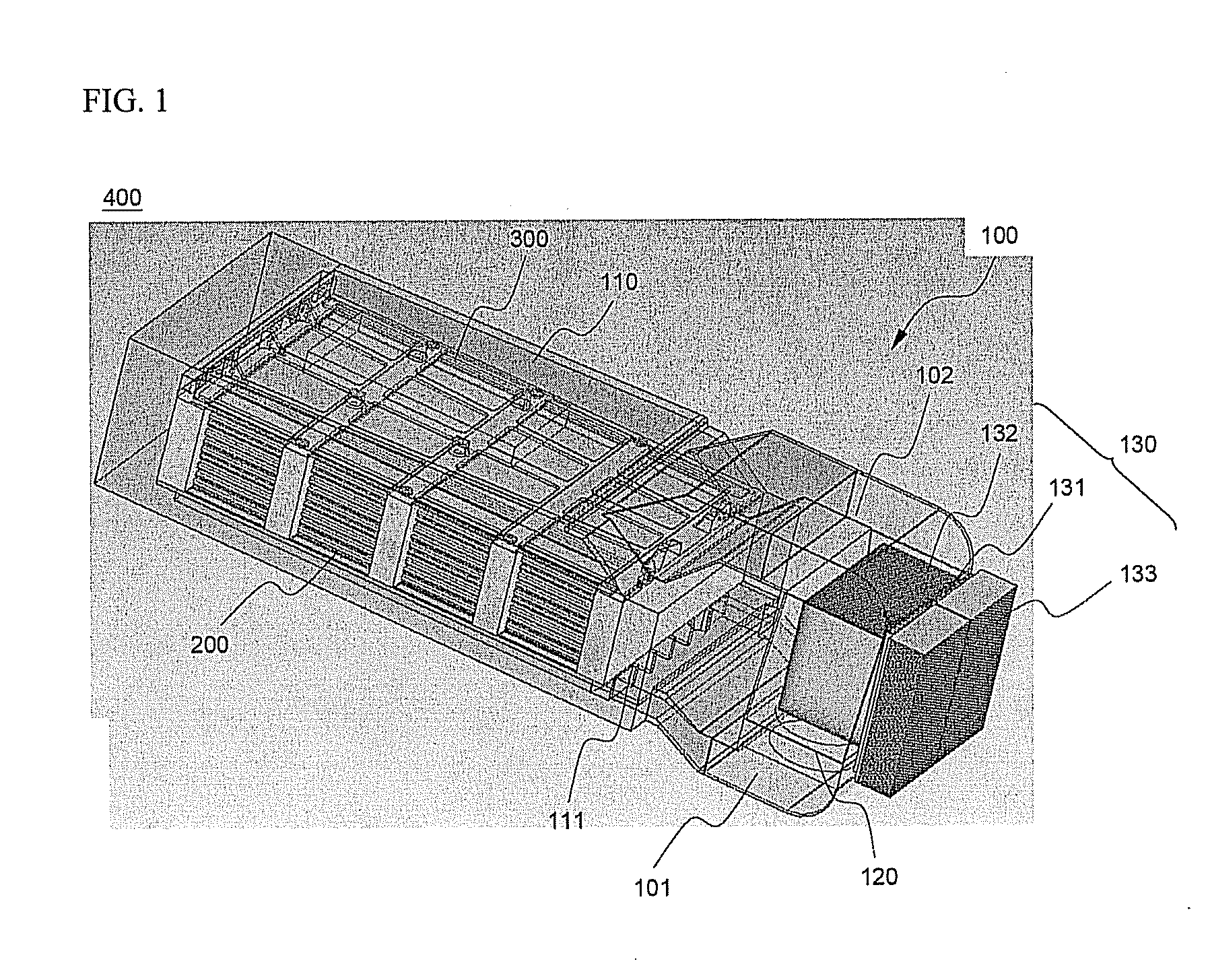
[0030]FIG. 1 is a perspective view illustrating a battery system including a sealed type heat exchange system according to the present invention.

[0031] Referring to FIG. 1, a battery system 400 is constructed in a structure in which a battery pack 200 and a control unit 300 are mounted in a heat exchange system 100.

[0032] The battery pack 200 is constructed in a structure in which a plurality of unit cells, such as pouch-shaped battery cells, are stacked one on another, and are then mounted to a sheathing member, such as a cartridge or a frame, while the unit cells are electrically connected with each other. The operation of the battery pack 200 is controlled by the control unit 300, for example, a battery management system (BMS).

[0033]...


PUM

PropertyMeasurementUnit
temperatureaaaaaaaaaa
heat conductivityaaaaaaaaaa
humidityaaaaaaaaaa

Abstract

Disclosed herein is a heat exchange system that controls the temperature of a medium- or large-sized battery pack including a plurality of unit cells. The heat exchange system includes a sealed type housing surrounding the outer surface of the battery pack such that a predetermined flow channel, through which a heat exchange medium flows, is defined between the housing and the battery pack, a driving fan mounted in the housing for driving the heat exchange medium to flow, and a heat exchange unit mounted at one side of the housing for controlling the temperature of the heat exchange medium. In the heat exchange system according to the present invention, the heat exchange medium, for example, air is not introduced from the outside of the battery system, but is circulated in the battery system by the heat exchange unit. Consequently, the present invention has the effect of accomplishing the reduction in size of the battery system, reducing influences caused by external conditions, decreasing noise, and effectively controlling the optimum operating temperature of the battery pack.

Description

FIELD OF THE INVENTION [0001] The present invention relates to a system that is capable of controlling the temperature of a medium- or large-sized battery pack including a plurality of unit cells, and, more particularly, to a heat exchange system for battery packs, including a sealed type housing surrounding the outer surface of the battery pack such that a predetermined flow channel, through which a heat exchange medium flows, is defined between the housing and the battery pack, a driving fan mounted in the housing for driving the heat exchange medium to flow, and a heat exchange unit mounted at one side of the housing for controlling the temperature of the heat exchange medium. BACKGROUND OF THE INVENTION [0002] One of the biggest problems caused from vehicles using fossil fuel, such as gasoline and diesel oil, is creation of air pollution. A technology of using a secondary battery, which can be charged and discharged, as a power source for vehicles has attracted considerable atte...

Claims


Application Information

Patent Timeline
Patent Type & Authority Applications(United States)
IPC IPC(8): H01M10/50H01M50/211
CPCH01M2/1016H01M2/1072H01M10/425H01M10/5004H01M10/5087H01M10/5067H01M10/5073H01M10/5085H01M10/5046H01M10/6563H01M10/6551H01M10/6572H01M10/6566H01M10/613H01M10/658Y02E60/10H01M50/211H01M50/20
Inventor AHN, JAESUNGPARK, JONGMINJUNG, DO YANGNAMGOONG, JOHN E.
Owner LG ENERGY SOLUTION LTD
Why Eureka
Try Eureka