Broadband beam steering antenna

a beam steering antenna and beam technology, applied in the direction of electrically short antennas, antennas, electrical apparatus, etc., can solve the problems of difficult integration in mobile devices (e.g. consumer electronic devices), relatively large size of phased array antennas, etc., to reduce power and energy, reduce battery size of mobile devices, and high antenna gain

Active Publication Date: 2008-10-02
SONY DEUT GMBH
View PDF5 Cites 14 Cited by
  • Summary
  • Abstract
  • Description
  • Claims
  • Application Information

AI Technical Summary

Benefits of technology

[0007]By providing a plurality of balanced radiation elements, a high antenna gain is provided. By providing a phase shifter device operable to apply the relative phase shifts, a plurality of radiation patterns (radiation beams) with different orientations are obtained, thus a beam steering antenna is provided. A high gain beam steering antenna reduces the power and energy needed, to operate an RF transmitter and / or receiver, thus, battery size of a mobile device can be reduced. Such antenna typically achieves a better reception in dead spots and is useful employed, for example, near walls (e.g. in a closed room) to achieve better signal reception and emission. By providing radiation elements in a planar structure, the antenna apparatus is small and is suitable for integration into mobile devices.
[0008]The RF transceiver according to the present invention comprises a transceiver front-end circuitry and an antenna apparatus according to the present invention wherein the transceiver front-end circuitry and the antenna apparatus are provided on a single printed circuit board. The inventive RF transceiver has, in addition to the advantages of the inventive antenna apparatus, the benefits of low cost of production, small size and high mechanical resistance (e.g. to shocks).

Problems solved by technology

However, phased array antennas are relatively large in size and their integration in mobile devices (e.g. consumer electronic devices) is very challenging.

Method used


Image

  • Broadband beam steering antenna
  • Broadband beam steering antenna
  • Broadband beam steering antenna

Examples


first embodiment

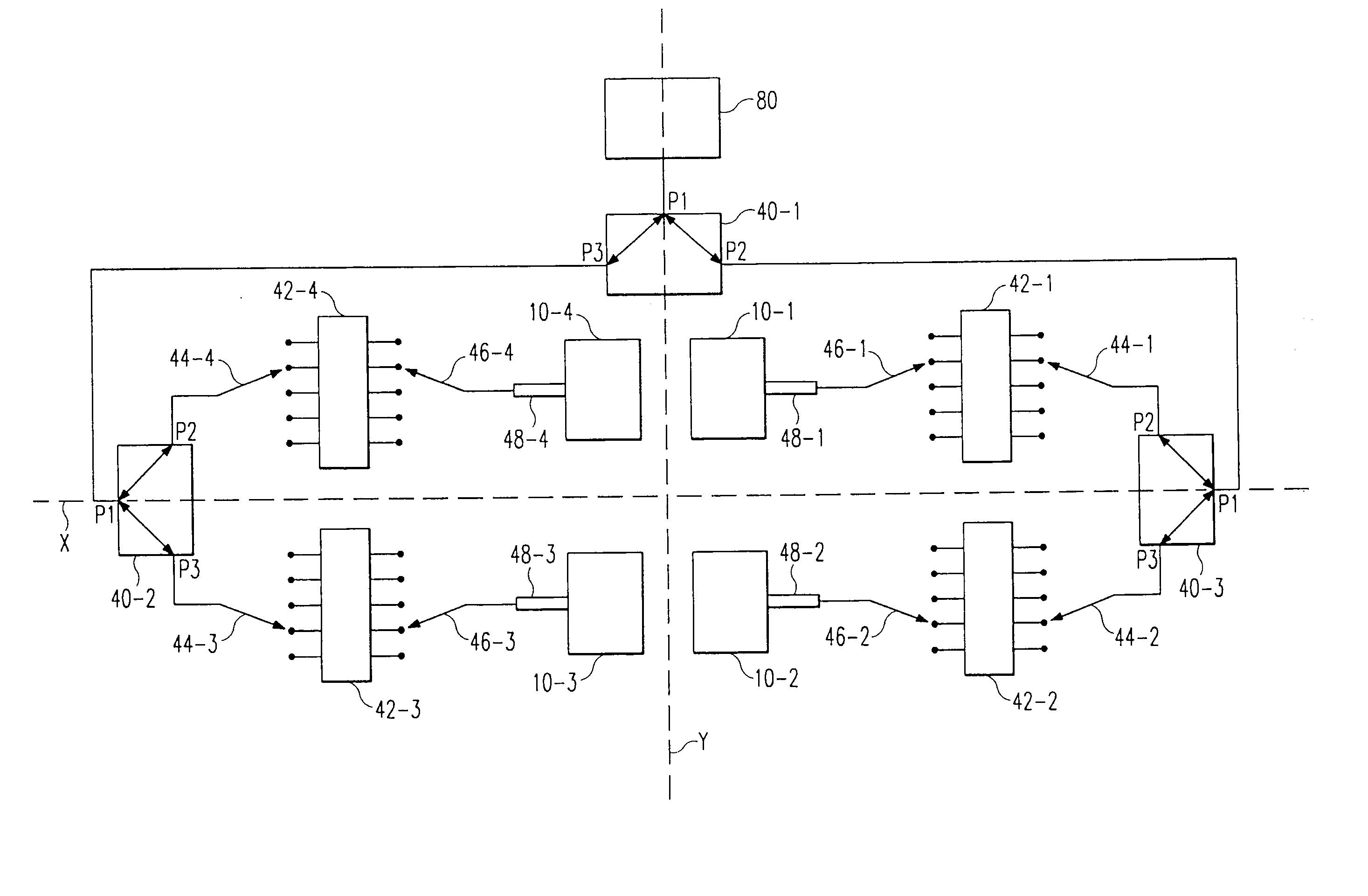
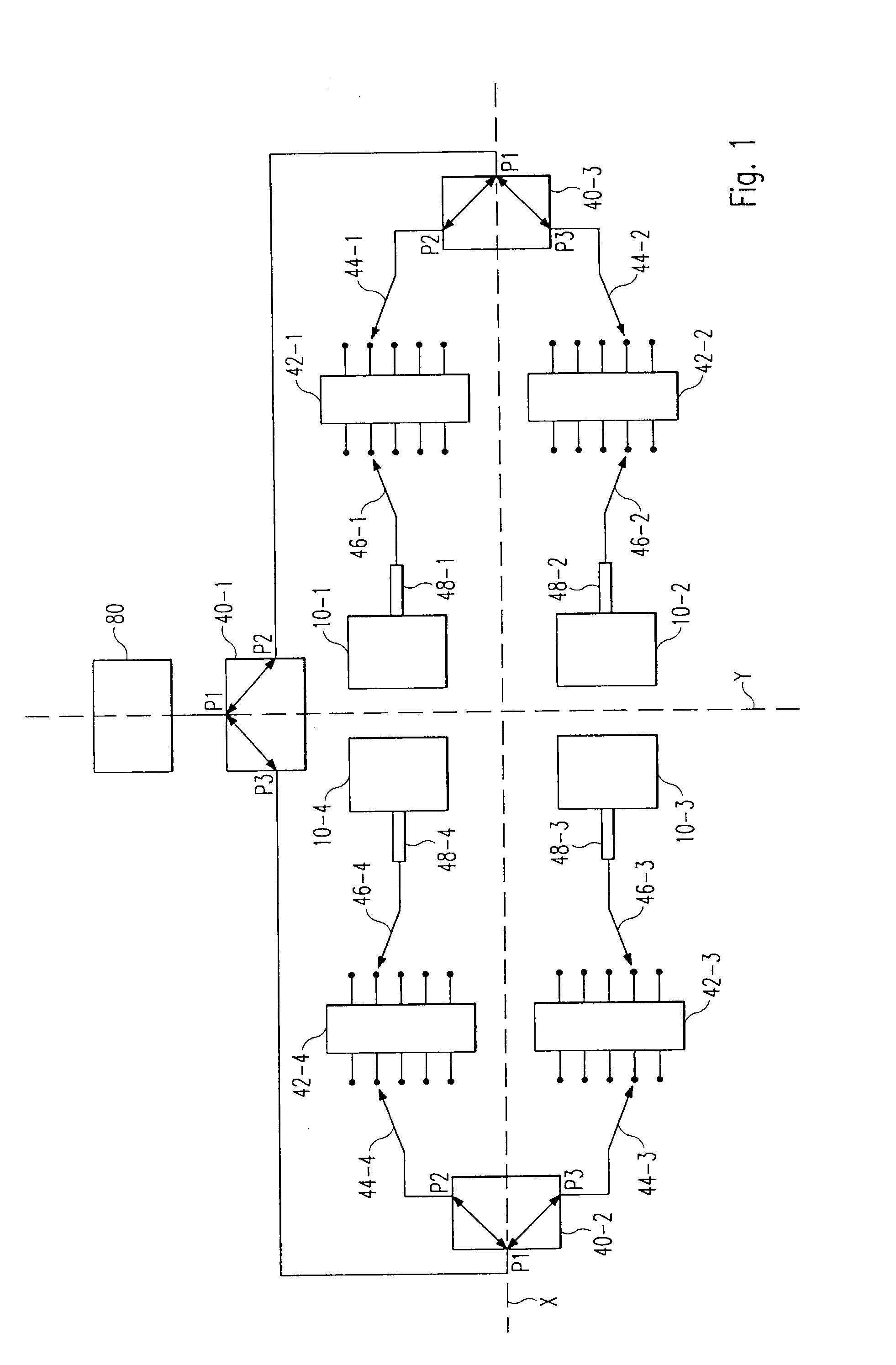
[0039]FIG. 1 shows a block diagram of an antenna apparatus 1 according to the present invention. The embodiment provides an ultra-wideband, high gain, directional beam steering antenna in the microwave spectrum. In this embodiment four radiation elements 10-1, 10-2, 10-3, 10-4 forming an array 24 of antennas are provided, however, two or more radiation elements are sufficient to implement the present invention. The antenna apparatus 1 receives and transmits an RF signal from and to the front-end of a transceiver circuitry 80. The embodiment described is designed for a center frequency f0 of the RF signal of 4 GHz and a bandwidth of 2 GHz. The present invention can, however, be profitably employed for (j frequency ranges other than 3 to 5 GHz and, especially, is not limited to the above mentioned regulatory frequency range of 3.1 to 10.6 GHz. In order to operate in a higher frequency band the antenna apparatus 1 has to be downsized and in order to operate in a lower frequency band th...

second embodiment

[0066]In a second embodiment, the antenna apparatus (2) is provided with a sandwiched structure as shown in FIG. 9. Here, at least part of the antenna feeding network 50 (i.e. the switches 44, 46, the phase shifter banks 42, the power splitter 38 and the interconnections) is located below the reflector element 26, thus a layered structure with the reflector element 26 in between the radiating elements 10-1, 10-2, 10-3, 10-4 and the feeding circuitry is obtained, which reduces the area needed for the antenna apparatus.

[0067]This layered structure can be integrated by filling the spaces between the network 50, the reflector plane 26 and the radiating elements 10 with electrically non-conducting material (insulator, semiconductor, . . . ). Thus the layered structure can be provided as a layered board structure.

[0068]The connection of the radiating elements 10 to the feeding circuitry may be around the reflector element 26 or by piercing the reflector element 26. Besides of this layer s...


PUM


Abstract

The present invention relates to an antenna apparatus with steerable beam pattern, an RF transceiver comprising the antenna apparatus and a mobile device comprising the antenna apparatus. The antenna apparatus according to the present invention is attachable to the front-end of a transceiver circuitry and comprises at least two balanced radiation elements forming a planar structure, for transmitting and/or receiving a corresponding number of partial signals, a signal splitter and/or combiner for splitting a signal received from an attached transceiver circuitry into said partial signals and/or combining said partial signals into a signal to be transmitted to an attached transceiver circuitry, a phase shifter device operable to apply relative phase shifts between at least two of said partial signals, whereby said relative phase shifts are selectable from a group of at least two relative phase shift values provided by said phase shifter device.

Description

FIELD OF THE INVENTION[0001]The present invention relates to an antenna apparatus with steerable beam pattern, an RF transceiver comprising the antenna apparatus and a mobile device comprising the antenna apparatus.DESCRIPTION OF THE RELATED PRIOR ART[0002]The American Federal Communications Commission (FCC) allows unlicensed use of the 3.1 GHz to 10.6 GHz frequency band for ultra-wideband (UWB) applications, whereby UWB refers to a broadband radio technology having a bandwidth larger than 500 MHz or larger than 25% of the center frequency. An ultra-wideband frequency range, for example, is a frequency range having a bandwidth larger than 500 MHz or larger than 25% of the center frequency. Other nations and organizations have followed and or are expected to follow the FCC regulations. The IEEE 802.15 working group develops standards for wireless short distance or wireless personal area networks. The group's WPAN™ technology employs the 3.1 GHz to 10.6 GHz range and addresses wireles...

Claims


Application Information

Patent Timeline
Patent Type & Authority Applications(United States)
IPC IPC(8): H01Q3/00
CPCH01Q3/2617H01Q9/285H01Q21/062H01P1/184
Inventor RATNI, MOHAMED
Owner SONY DEUT GMBH
Why Eureka
Try Eureka