Array antenna

a technology of array antenna and antenna array, which is applied in the direction of antennas, electrical devices, individually energised antenna arrays, etc., can solve the problems of increasing the number of targets to be subjected to phase shift control, the array antenna cannot be made to operate as an active phased array antenna, and the beam steering cannot be performed in this direction, so as to achieve high antenna gain

Inactive Publication Date: 2018-10-25
MURATA MFG CO LTD
View PDF25 Cites 4 Cited by
  • Summary
  • Abstract
  • Description
  • Claims
  • Application Information

AI Technical Summary

Benefits of technology

[0008]An object of the present disclosure is to provide an array antenna that can perform beam steering in both an azimuth direction and an elevation direction, can suppress an increase in the number of targets to be subjected to phase shift control, and that can obtain high antenna gain.
[0010]A high-frequency signal can be supplied to the plurality of sub-arrays via the power feeding lines while applying a desired phase difference. Thus, beam steering can be performed with respect to the first direction and the second direction. Since the plurality of sub-arrays are arranged in the second direction so as to be shifted with respect to each other in the first direction, the effective pitch of the sub-arrays with respect to the first direction as a whole is smaller than the pitch of the sub-arrays of one row arranged in the first direction. As a result, the beam swing angle with respect to the first direction can be made large. One input / output terminal of the high-frequency input / output device is connected to a plurality of radiating elements included in one sub-array, and therefore a greater number of radiating elements can be arranged than the number of input / output terminals. Due to the number of radiating elements being increased, a high antenna gain can be obtained. In other words, even though the number of radiating elements is increased, an increase in the number of input / output terminals of the high-frequency input / output device can be suppressed.

Problems solved by technology

Therefore, the array antenna cannot be made to operate as an active phased array antenna.
Although the desired coverage can be provided in the direction perpendicular to the array direction by applying a prescribed phase difference, beam steering cannot be performed in this direction.
In addition, when the number of radiating elements is increased in order to obtain high antenna gain, the number of targets that are to be subjected to phase shift control is increased and the high-frequency circuit becomes more complex.

Method used


Image

  • Array antenna
  • Array antenna
  • Array antenna

Examples


first embodiment

[0027]An array antenna according to a first embodiment will be described while referring to FIGS. 1A to 2B.

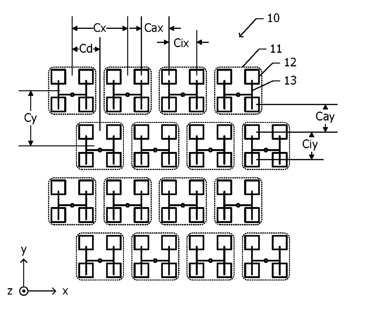
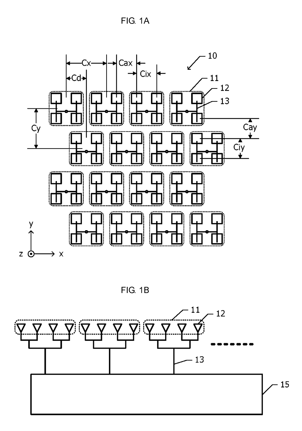
[0028]FIG. 1A is a plan view of an array antenna according to a first embodiment. An array antenna 10 according to the first embodiment includes a plurality of sub-arrays 11 that are two-dimensionally arranged in an x direction and a y direction, which are perpendicular to each other. For example, a total of sixteen, i.e., four in the x direction and four in the y direction, sub-arrays 11 are arranged. Each of the plurality of sub-arrays 11 includes four radiating elements 12 that are arranged in a two-row by two-column matrix in which the x direction is a row direction and the y direction is a column direction. Patch antennas are used as the radiating elements 12.

[0029]The arrangement of the radiating elements 12 inside the sub-arrays 11 is the same in the plurality of sub-arrays 11. A high-frequency signal is supplied to each radiating element 12 via power feeding lines 13 th...

second embodiment

[0044]Next, an array antenna 10 according to a second embodiment will be described while referring to FIG. 3. Hereafter, the description of the parts of the configuration that are identical to those of the array antenna 10 according to the first embodiment illustrated in FIGS. 1A to 2B is omitted.

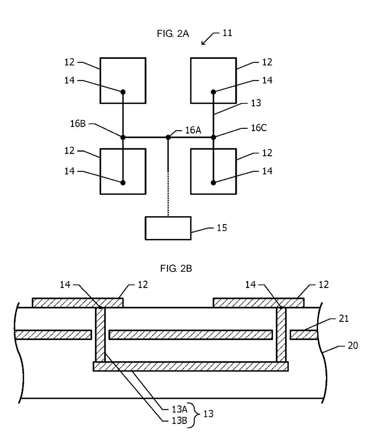
[0045]FIG. 3 is a plan view illustrating one sub-array 11 and a part of a power feeding line 13 of the array antenna 10 according to the second embodiment. In the first embodiment, the power feeding points 14 are arranged at positions that are shifted in the same direction from the centers of the radiating elements 12 in all of the radiating elements 12 (FIG. 2A) inside one sub-array 11. In the second embodiment, in any two radiating elements 12 that are adjacent to each other in the y direction, the power feeding points 14 are arranged at positions that are shifted by the same distance in directions such that the power feeding points 14 move closer to each other from the centers of the rad...

third embodiment

[0048]Next, an array antenna 10 according to a third embodiment will be described while referring to FIGS. 4A to 4C. Hereafter, the description of the parts of the configuration that are identical to those of the array antenna 10 according to the first embodiment illustrated in FIGS. 1A to 2B is omitted.

[0049]FIG. 4A is a plan view of one sub-array 11 of the array antenna 10 according to the third embodiment. In the first embodiment, one sub-array 11 includes four radiating elements 12 (FIG. 1A), whereas in the third embodiment, one sub-array 11 includes eight radiating elements 12. The eight radiating elements 12 are arranged in a four-row by two-column matrix. The power feeding line 13, which is connected to the high-frequency input / output device 15, extends to each of the plurality of radiating elements 12 via three branching points.

[0050]As illustrated in FIG. 4A, the directivity with respect to the y direction can be made sharper by arranging a greater number of radiating eleme...


PUM


Abstract

Provided is an array antenna in which a plurality of sub-arrays, which each include a plurality of radiating elements, are two-dimensionally arranged in a first direction and a second direction, which are perpendicular to each other. A plurality of power feeding lines individually feed power from a high-frequency input / output device to each of the plurality of sub-arrays. The plurality of sub-arrays are arranged along straight lines in the first direction, and are arranged in the second direction such that among two sub-arrays that are adjacent to each other in the second direction, one sub-array is shifted in the first direction with respect to the other sub-array.

Description

[0001]This application claims priority from Japanese Patent Application No. 2017-085531 filed on Apr. 24, 2017. The content of this application is incorporated herein by reference in its entirety.BACKGROUND OF THE DISCLOSURE1. Field of the Disclosure[0002]The present disclosure relates to an array antenna.2. Description of the Related Art[0003]Array antennas are disclosed in International Publication No. 2010 / 089941 and Japanese Unexamined Patent Application Publication (Translation of PCT Application) No. 2010-541315. The array antenna disclosed in International Publication No. 2010 / 089941 includes first antenna elements that are arranged at a prescribed element interval and second antenna elements that are arranged at the same element interval so as to be parallel to the arrangement direction of the first antenna elements. Power is supplied to the first antenna elements via lines that branch at a first branching point, and power is supplied to the second antenna elements via lines...

Claims


Application Information

Patent Timeline
Patent Type & Authority Applications(United States)
IPC IPC(8): H01Q21/06H01Q3/24H01Q3/34H01Q9/04
CPCH01Q21/06H01Q3/24H01Q3/34H01Q9/04H01Q1/50H01Q21/0006H01Q21/061H01Q9/0407H01Q21/0075H01Q21/065H01Q21/293
Inventor SUDO, KAORU
Owner MURATA MFG CO LTD
Why Eureka
Try Eureka