Radar device

a radar device and antenna technology, applied in the direction of reradiation, printed circuit non-printed electric components association, instruments, etc., can solve the problems of difficult to achieve antenna gain and insufficient azimuth resolution capability for detecting objects, so as to reduce the space for mounting the radar device and enhance the degree of freedom in selecting a position

Inactive Publication Date: 2019-05-30
PANASONIC INTELLECTUAL PROPERTY MANAGEMENT CO LTD
View PDF0 Cites 4 Cited by
  • Summary
  • Abstract
  • Description
  • Claims
  • Application Information

AI Technical Summary

Benefits of technology

[0004]As such a radar device, a radar device mounted in a lateral direction, in which a circuit board on which an antenna unit is mounted is arranged parallel to a direction of transmitting electromagnetic waves, has been recently under consideration from the viewpoints of, for example, reducing a space for mounting the radar device and enhancing a degree of freedom in selecting a position for mounting the radar device.
[0007]One non-limiting and exemplary embodiment provides a radar device that has a device configuration of being mounted in a lateral direction and achieves high antenna gain and high azimuth resolution capability.
[0009]The radar device according to the present disclosure may have a device configuration of being mounted in a lateral direction and achieve high antenna gain and high azimuth resolution capability.

Problems solved by technology

However, the radar device discussed in PTL 1 has a problem in that the azimuth resolution capability for detecting the object is insufficient because the directions of transmitting the electromagnetic waves are limited to the directions that the respective end-fire antennas face.
The radar device disclosed in PTL 1 has also a problem in that it is difficult to achieve the antenna gain.

Method used


Image

  • Radar device
  • Radar device
  • Radar device

Examples


first embodiment

[0025]An example of a configuration of a radar device according to this embodiment is described with reference to FIGS. 1 to 4. Hereinafter, a vehicle-mounted radar device is described as an example of a usage example of the radar device of the present disclosure.

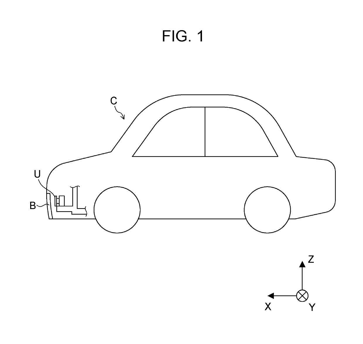
[0026]FIG. 1 is a diagram illustrating a radar device U according to this embodiment disposed in a vehicle.

[0027]For example, the radar device U according to this embodiment is disposed in a cover member B (here, a bumper member B) of a vehicle C and performs transmission and reception of electromagnetic waves through the cover member B.

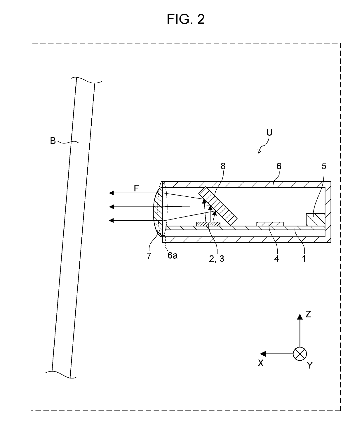
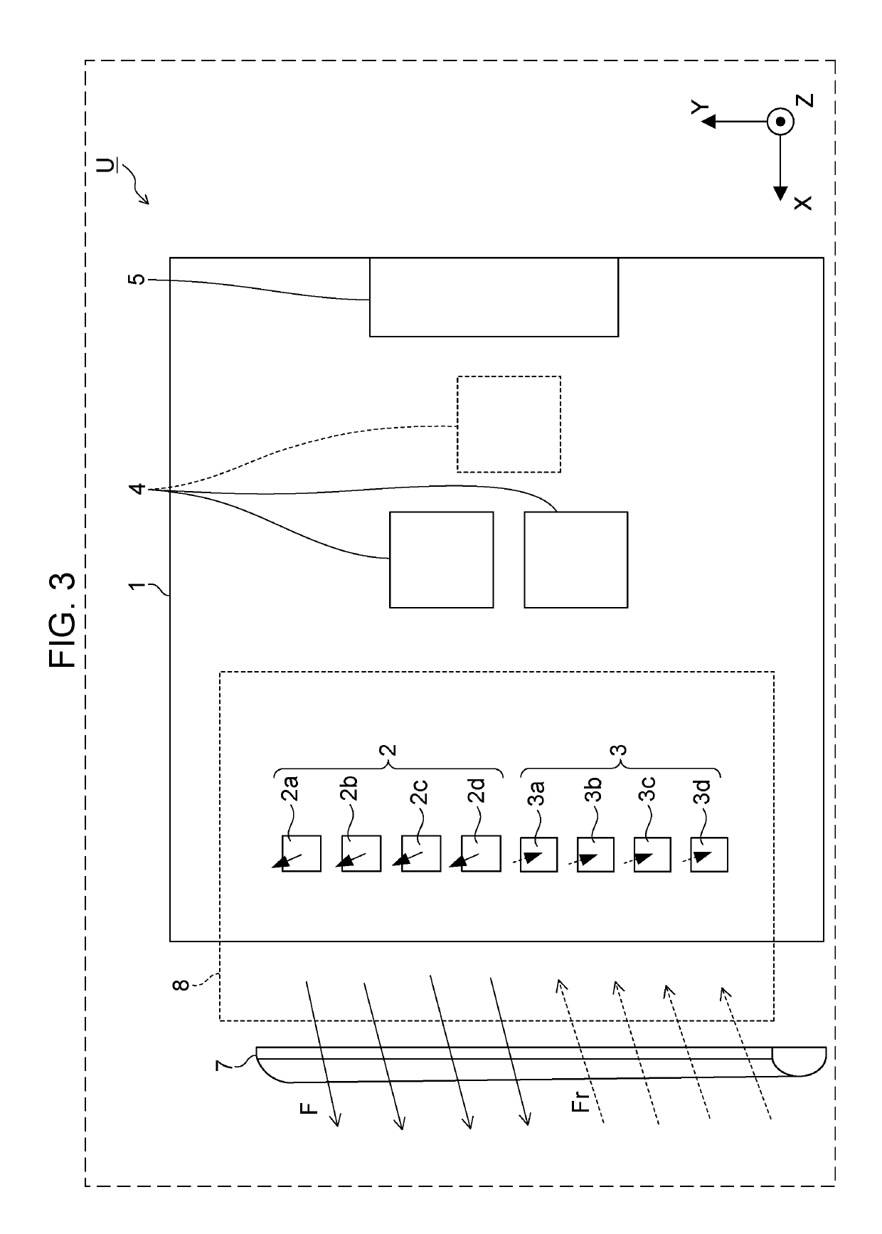
[0028]FIG. 2 is a side sectional view of the radar device U according to the first embodiment. FIG. 3 is a view of the radar device U according to the first embodiment seen from above.

[0029]Solid arrows F in FIGS. 2 and 3 represent the electromagnetic waves transmitted by a transmitting antenna. Dotted line arrows Fr represent the reflected waves from the target. In FIGS. 2 and 3, illustrati...

second embodiment

[0073]Next, an example of a configuration of a radar device U according to a second embodiment is described with reference to FIG. 5.

[0074]FIG. 5 is a side sectional view of the radar device U according to the second embodiment.

[0075]The radar device U according to this embodiment is different from the radar device U according to the first embodiment in that the radar device U according to this embodiment has a bracket 9 for fixing the housing 6 and the like to the cover member B. Descriptions of configurations common to the first embodiment are omitted (the same applies hereinafter for other embodiments).

[0076]The bracket 9 holds the housing 6 with respect to the cover member B and defines the direction in which the radar device U transmits and receives the electromagnetic waves.

[0077]The bracket 9 has, for example, a storage part 9a that stores the radar device U and fixing parts 9b that are fixed to the cover member B.

[0078]For example, the storage part 9a is in a cylindrical sha...

third embodiment

[0083]Next, an example of a configuration of a radar device U according to a third embodiment is described with reference to FIG. 6.

[0084]FIG. 6 is a side sectional view of the radar device U according to the third embodiment.

[0085]The radar device U according to this embodiment is different from the radar device U according to the first embodiment in that the housing 6 has connection units 6b that are thermally bonded to the circuit board 1 or circuit parts (e.g., signal processing ICs 4) mounted on the circuit board 1.

[0086]FIG. 6 illustrates a state where the connection units 6b thermally bond the wall of the housing 6 and the circuit board 1. White arrows in FIG. 6 represent heat flows from the circuit board 1.

[0087]In this embodiment, a metal member with high heat dissipation characteristics is used as the material of the housing 6, for example. The connection units 6b then thermally bond the wall of the housing 6 and the circuit board 1 or the circuit parts mounted on that cir...


PUM


Abstract

A radar device includes: an antenna unit including antenna elements arrayed along a direction intersecting a front direction in a circuit board, transmitting an electromagnetic wave upward of a board surface of the circuit board, and receiving a reflected wave of the electromagnetic wave; a reflection unit supported above the board surface of the circuit board in a housing, reflecting the electromagnetic wave transmitted from the antenna unit to change a traveling direction of the electromagnetic wave to the front direction, and reflecting the reflected wave from the front direction to change a traveling direction of the reflected wave to a direction toward the antenna unit; and a dielectric lens disposed in an aperture of the housing to extend along a direction in which the antenna elements are arrayed, and having a semi-cylindrical shape or a parabolic-cylindrical shape projecting in the front direction.

Description

BACKGROUND1. Technical Field[0001]The present disclosure relates to a radar device.2. Description of the Related Art[0002]A radar device has been known, which uses electromagnetic waves in a frequency band of millimeter-waves and microwaves to detect a position of an object (hereinafter also referred to as “target”) without contact.[0003]Such radar device is, for example, mounted in a vehicle and used for monitoring multiple directions including a front direction, front-side directions, and rear-side directions.SUMMARY[0004]As such a radar device, a radar device mounted in a lateral direction, in which a circuit board on which an antenna unit is mounted is arranged parallel to a direction of transmitting electromagnetic waves, has been recently under consideration from the viewpoints of, for example, reducing a space for mounting the radar device and enhancing a degree of freedom in selecting a position for mounting the radar device.[0005]For example, Japanese Unexamined Patent Appl...

Claims


Application Information

Patent Timeline
Patent Type & Authority Applications(United States)
IPC IPC(8): H01Q19/06H01Q1/42H01Q9/04H01Q19/10H01Q1/32H05K1/02H05K1/18H05K7/14G01S7/03G01S13/93H01Q3/34G01S13/931
CPCH01Q19/06H01Q1/42H01Q9/0407H01Q19/10H01Q1/3275H05K1/0243H05K1/181H05K7/1427G01S7/032G01S13/931H01Q3/34H05K2201/10098G01S2013/9382G01S2013/9371H01Q1/3233H01Q1/3283H01Q15/08H01Q15/14H01Q19/062H01Q21/08G01S7/027G01S2013/9327G01S2013/93273
Inventor SHIOZAKI, RYOSUKEYUI, TOMOHIROTAKAHASHI, KENKASHINO, YUICHISUZUKI, KOUJISAITO, NORIAKINAKAMURA, SHIGEKI
Owner PANASONIC INTELLECTUAL PROPERTY MANAGEMENT CO LTD
Why Eureka
Try Eureka