Magnetoelectric Antenna Arrays

a magnetic antenna and array technology, applied in waveguide devices, instruments, using wave/particle radiation means, etc., can solve the problems of becoming very difficult for electronic engineers to miniaturize antennas, and achieve high antenna gain, strong ground plant immunity, and large bandwidth

Pending Publication Date: 2022-02-03
NIAN XIANG SUN +2
View PDF0 Cites 1 Cited by
  • Summary
  • Abstract
  • Description
  • Claims
  • Application Information

AI Technical Summary

Benefits of technology

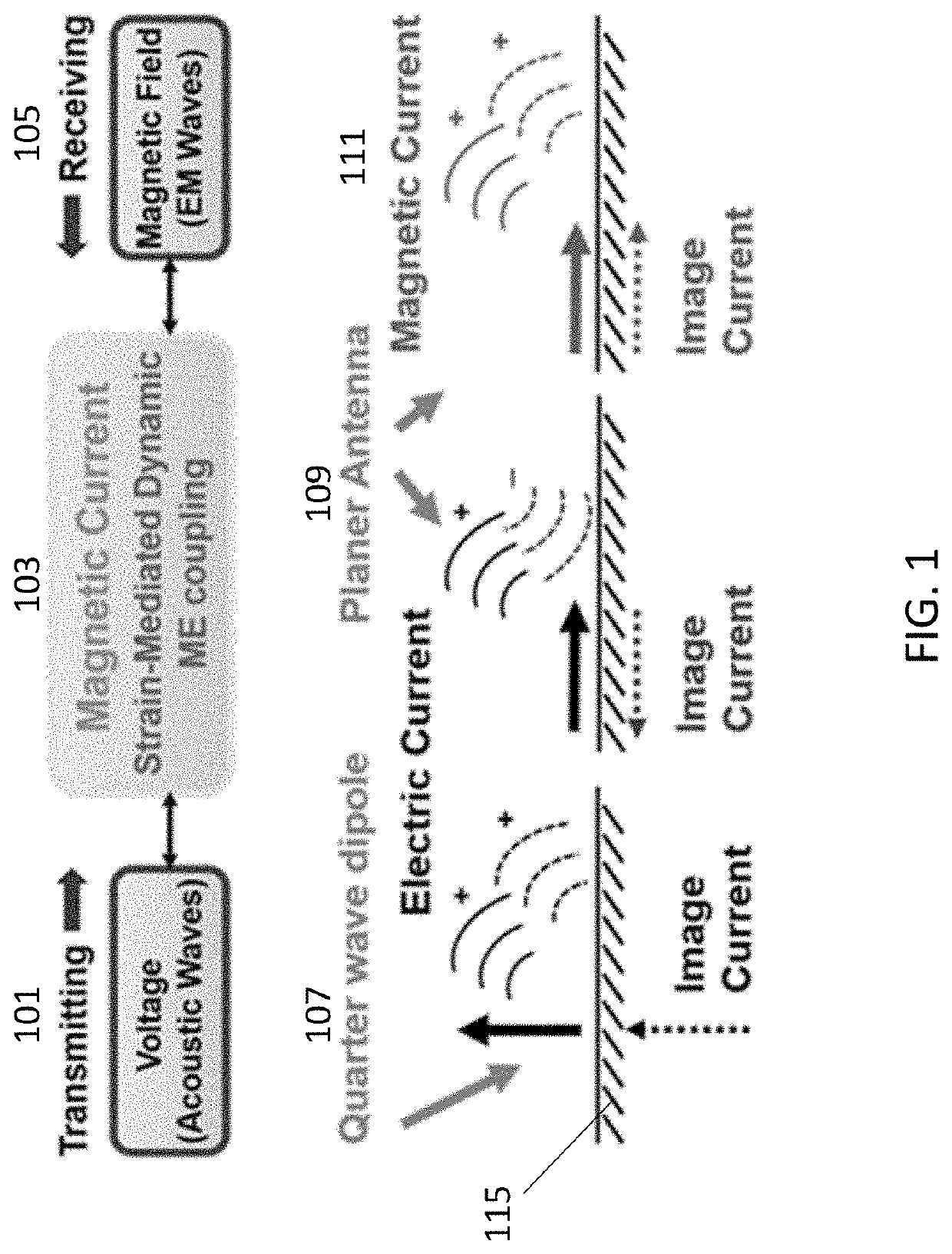
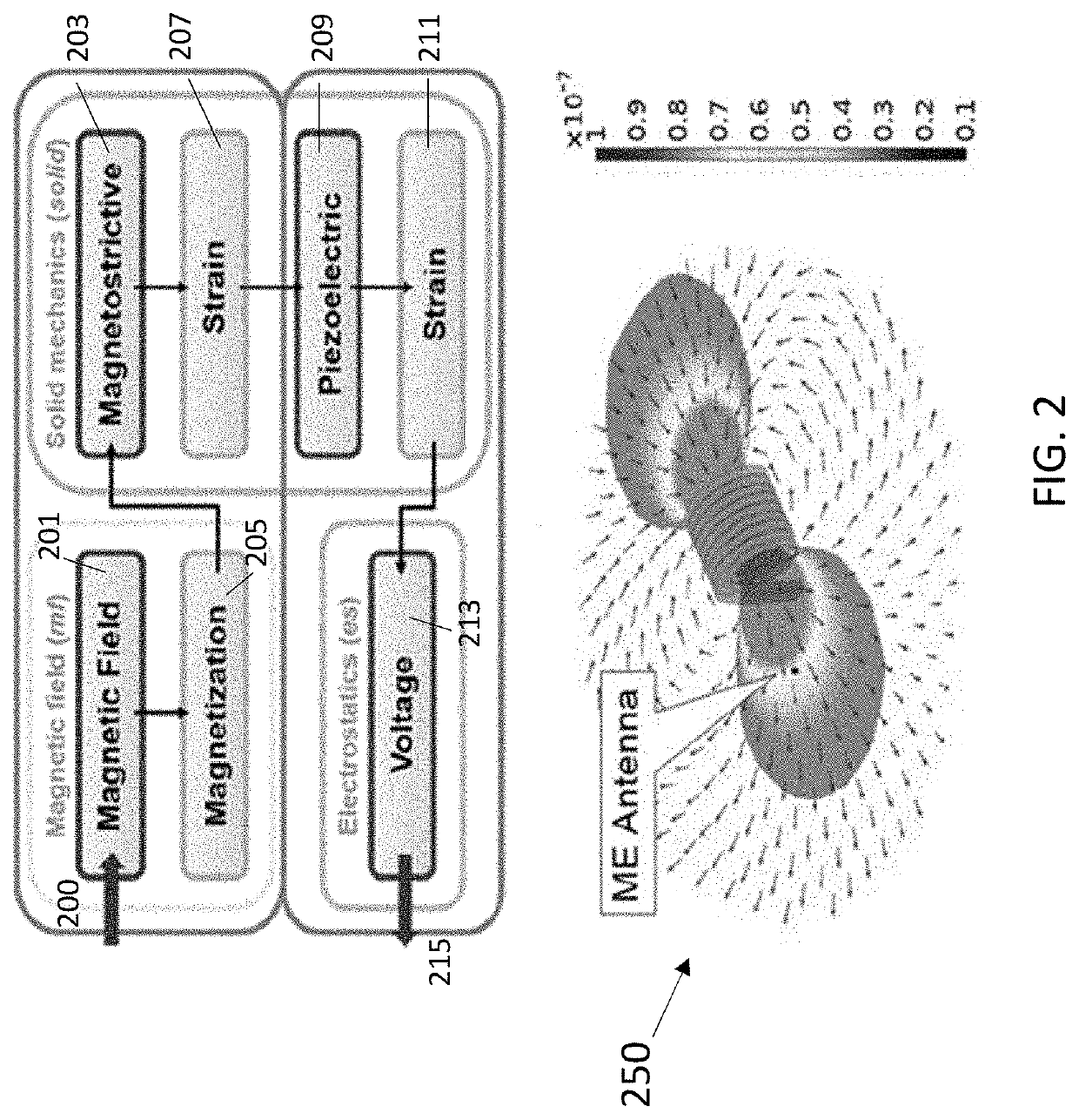
[0016]In one embodiment, the piezoelectric layer crossing over an aperture structure, with out-of-plane excitation, allows for in-plane and out-of-plane vibration, while the magnetic layer also allows for in-plane and out-of-plane vibrations. Voltage-induced acoustic waves induce magnetization dynamics in the thin film heterostructure through the magnetoelectric coupling, leading to radiation of electromagnetic waves at the a...

Problems solved by technology

With fixed transmission wavelength, it has become very challenging for electronic engineers to miniaturize antennas, particularly for the applications...

Method used


Image

  • Magnetoelectric Antenna Arrays
  • Magnetoelectric Antenna Arrays
  • Magnetoelectric Antenna Arrays

Examples


Embodiment Construction

[0036]Reference will now be made in detail to embodiments of the invention. Wherever possible, same or similar reference numerals are used in the drawings and the description to refer to the same or like parts or steps. The drawings are in simplified form and are not to precise scale. The word ‘couple’ and similar terms do not necessarily denote direct and immediate connections but also include connections through intermediate elements or devices. For purposes of convenience and clarity only, directional (up / down, etc.) terms may be used with respect to the drawings. These and similar directional terms should not be construed to limit the scope in any manner. It will also be understood that other embodiments may be utilized without departing from the scope of the present invention, and that the detailed description is not to be taken in a limiting sense, and that elements may be differently positioned, or otherwise noted as in the appended claims without requirements of the written ...


PUM


Abstract

Two or more ME resonators are connected in series and in parallel generating a high sensitive, energy efficient and broadband miniature antenna and other conductor devices.

Description

CROSS REFERENCES[0001]Priority is claimed from U.S. Provisional Application No. 63 / 115148, filed on Nov. 18. 2020, entitled “Magnetoelectric Antenna Arrays,” the entirety of which is hereby incorporated by reference; and this application is also a continuation in part of U.S. patent application Ser. No. 16 / 304,802, filed on May 31, 2017 entitled “Nanoscale Radio Frequency Magnetoelectric Antenna”, the entirety of which is hereby incorporated by reference.BACKGROUNDField of the Invention[0002]The present patent application relates to a type of ultra-compact and efficient antennas for use in wireless communication systems, Bio-medical applications, satellite and radar systems. More particularly, the present patent application describes an antenna comprising of arrays of resonators connected in series and / or in parallel that is capable of receiving electromagnetic (EM) signals from an AC source operating anywhere from kHz to GHz frequency with improved radiation efficiency and bandwidt...

Claims


Application Information

Patent Timeline
IPC IPC(8): H03H9/17H03H9/22H03H9/13H03H9/135G01R33/02G01H9/00
CPCH03H9/171H03H9/22G01H9/00H03H9/135G01R33/02H03H9/13H01Q21/00H01Q1/38H01P7/00G01R33/0286H03H9/173H03H9/175H03H9/62H01Q21/061H01Q1/364
Inventor SUN, NIAN XIANGLIN, HWAIDER
Owner NIAN XIANG SUN
Why Eureka
Try Eureka