Cannulated Bone Screw

a bone screw and cannula technology, applied in the field of bone screws, can solve the problems of large amount of screw stripping, and large amount of screw stripping, and achieve the effect of removing the whole screw stripping, high strength, and excessive application

US20070250063A1Active Publication Date: 2007-10-25PIONEER SURGICAL TECH INC
5 Cites 4 Cited by

Patent Information

Authority / Receiving Office
US · United States
Patent Type
Applications(United States)
Current Assignee / Owner
Publication Date
2007-10-25

Smart Images

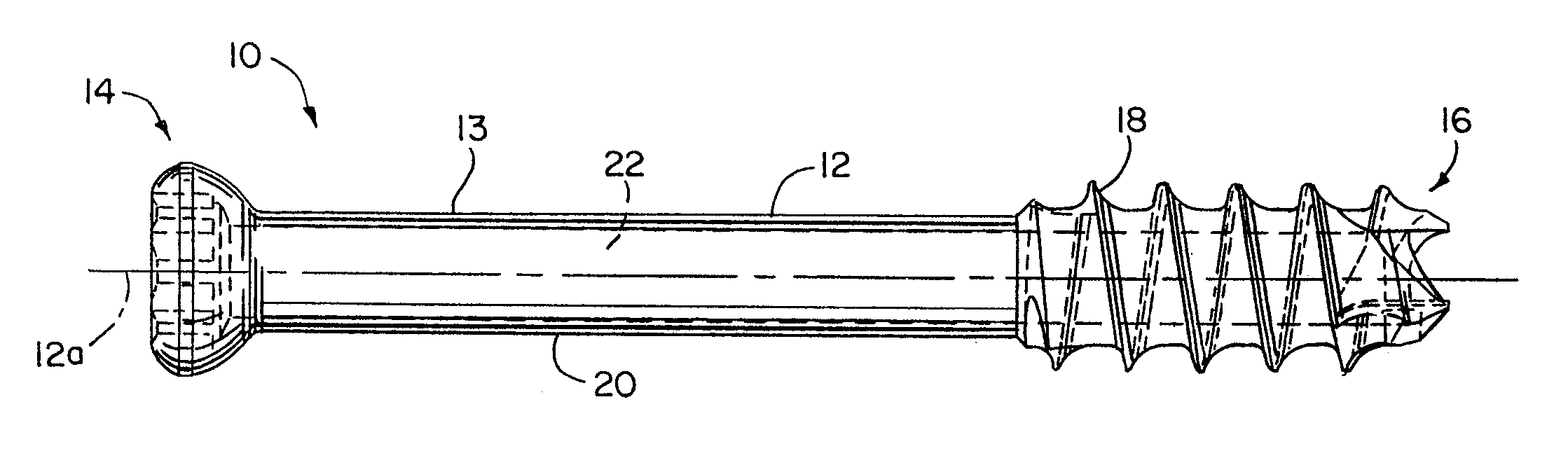
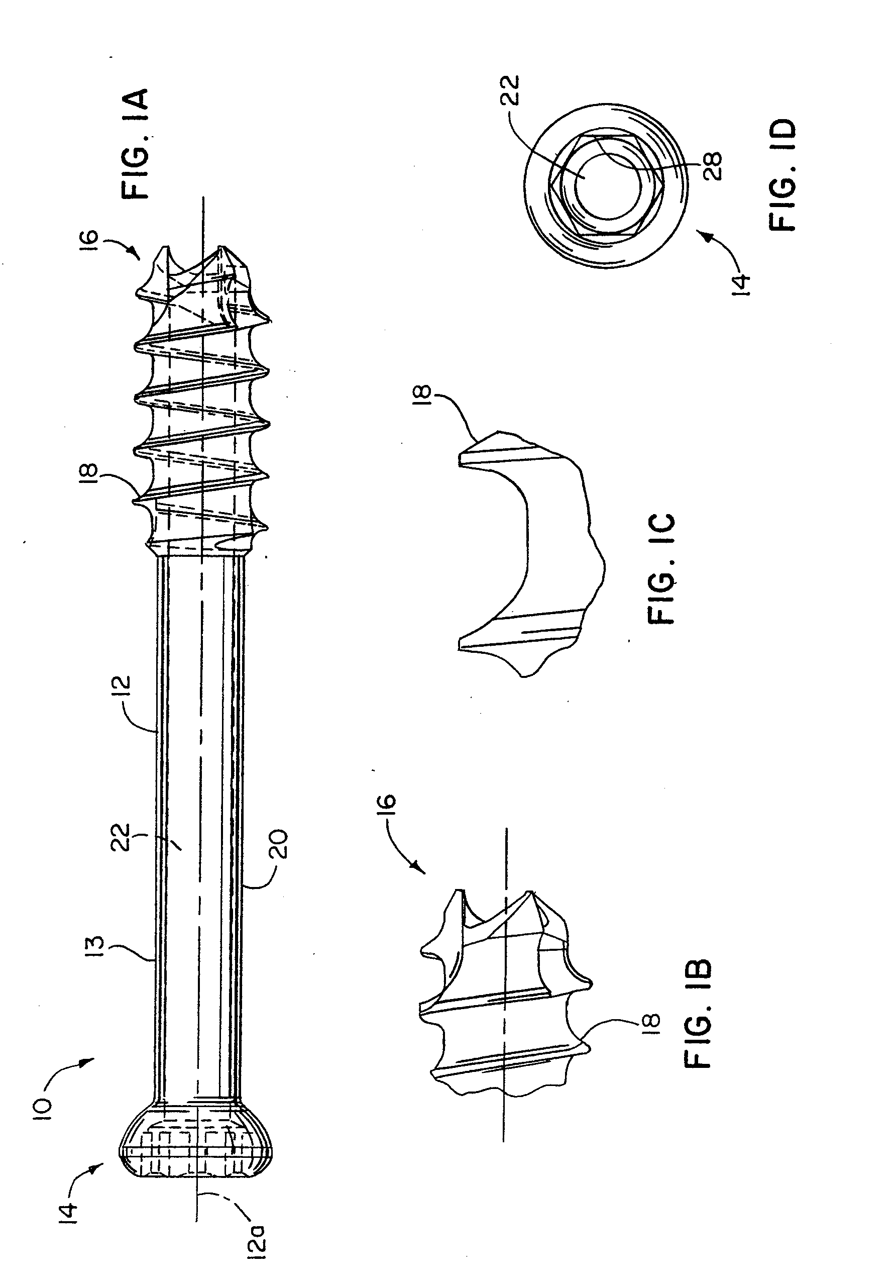
  • Figure 1
    Figure 1
  • Figure 2
    Figure 2
  • Figure 3
    Figure 3
Patent Text Reader

Abstract

A small cannulated bone screw is provided having an optimized combination of strength, cannula size and thread depth. A set of such strong and small size screws is also provided where the smallest sizes can have one performance ratio emphasized over another, and the larger sizes can have the emphasis reversed. In particular, the smallest screws optimize the combination of their strength and cannula size with the larger screws optimizing the combination of their strength and thread depth. In any event, each of the screws in the set has an optimized combination of strength, cannula size and thread depth throughout the full range of screw sizes in the set, e.g. 3.0 mm to 7.5 mm major diameters.
Need to check novelty before this filing date? Find Prior Art

Description

FIELD OF THE INVENTION

[0001] The invention relates to bone screws and, more particularly, to small bone screws that are cannulated. BACKGROUND OF THE INVENTION

[0002] Cannulated bone screws provided with an axial throughbore or cannula extending therethrough are known to allow use of guide wires that penetrate a bone at the desired implant site for the screw and guide the screw as it is being rotatably driven into the bone. One well known problem with bone screws is that as they start to go down in size in terms of the outer diameter of their threads, i.e., major diameter, the cannulas thereof likewise become very small so that only very thin guide wires can be used therewith. These thin guide wires are fairly flimsy and thus tend to bend and buckle, and walk on the surface of the bone when being inserted into the bone material. When this occurs, the location and / or angle of penetration varies from that which is desired making for inaccuracies in implanting the screw. In some insta...

Examples

Embodiment Construction

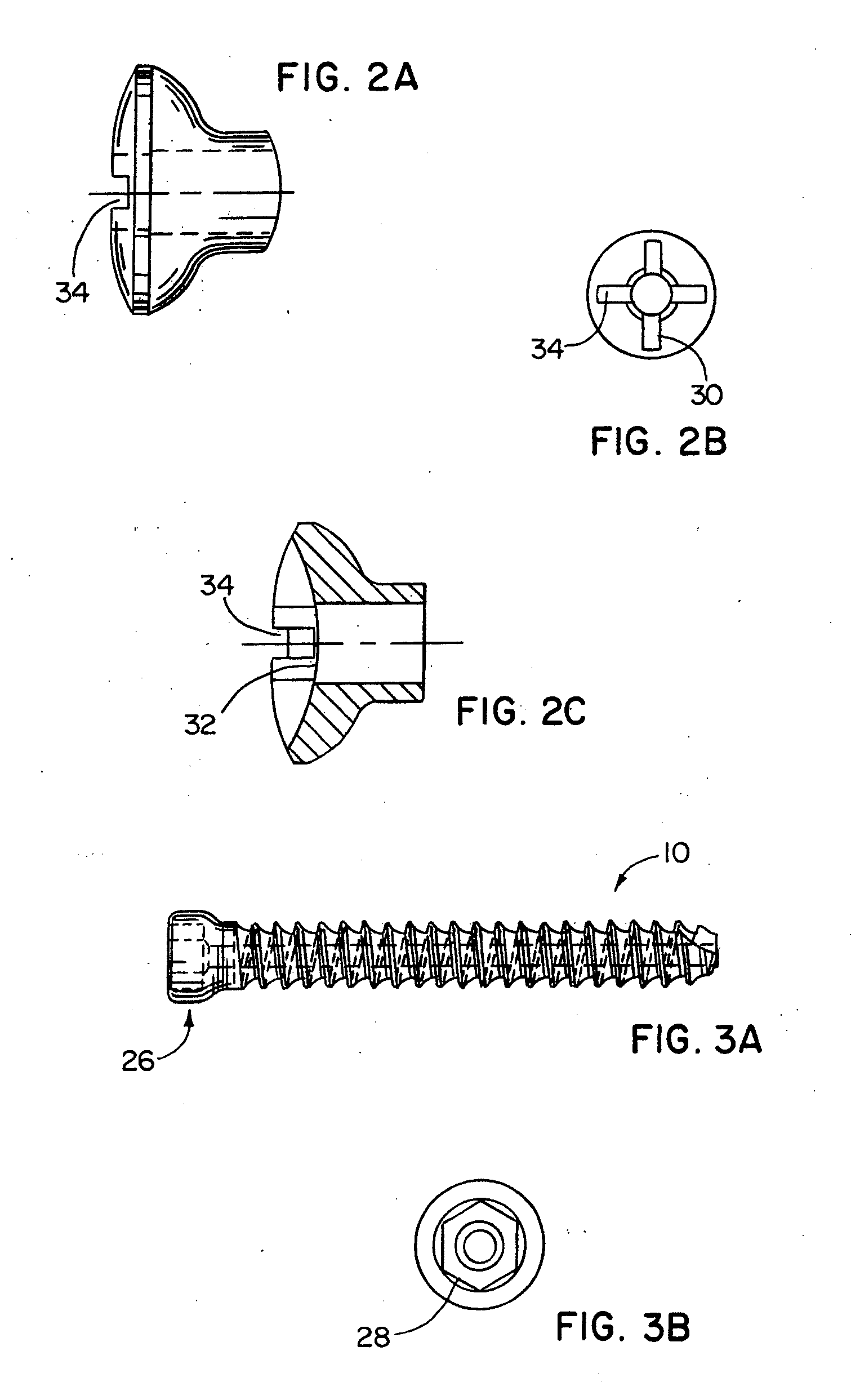
[0019] In FIGS. 1A-1D, a screw apparatus 10 in the form of bone screw 10a for being implanted into bone material is shown having one preferred configuration thereof. The bone screw apparatus 10 has an elongate shank 12 having proximal and distal ends 14 and 16, respectively. The shank 12 has external threads 18 formed along the shank 12 between the ends 14 and 16 thereof. As shown in the screw 10 of FIG. 1A, the screw shank 12 is only partially threaded from the distal self-tapping and self-drilling end 16 to approximately mid-way along the length of the shank 12 leaving an unthreaded section 20 thereof. Alternatively, the entire length of the shank 12 less screw head 26 can be threaded, as shown in FIG. 3A.

[0020] Referring to FIG. 4 and taking measurements for one of the listed screws 10, the thread outer or major diameter can be approximately 0.138 inches or 3.5 millimeters. As can be seen in FIGS. 1A and 1D, the shank 12 has a generally annular wall 13 including a throughbore or...