Cannulated bone screw

a bone screw and cannula technology, applied in the field of bone screws, can solve the problems of large amount of screw stripping, and large amount of screw stripping, and achieve the effect of reducing the amount of screw stripping

Active Publication Date: 2007-04-24
PIONEER SURGICAL TECH INC
View PDF1 Cites 35 Cited by
  • Summary
  • Abstract
  • Description
  • Claims
  • Application Information

AI Technical Summary

Benefits of technology

[0007]In accordance with the present invention, small cannulated bone screws are provided that are optimized in terms of their bending and torsional strength while still allowing for their implantation using relatively large diameter guide wires. To this end, the screws have a cannula that is maximized in size without a significant performance-related sacrifice such as in their strength characteristics. Also, the thread purchase of the small screws herein can be maximized so that the screws also have good pull-out resistance, as described further hereinafter.
[0011]As previously described, screw breakage during implantation is a problem particularly at the small sizes for bone screws that the present invention addresses. With the high strength provided to the present bone screws, and particularly to the annular wall extending along the shank thereof, it has been found that with excessive applied torque to the screw at the screw head driving surfaces, as when bone material becomes harder or increasingly difficult to penetrate with the preferred self-tapping screws herein, rather than shearing of the screw shank, the screw is stripped as by deformation of the driving surfaces. In this manner, the present screws do not break into distinct portions as often occurs with prior small bone screws before stripping. Thus, there is not the problem of having to locate the broken off portion or pieces of screws at or around the implantation site during a surgical operation employing the small bone screws herein, and removal of the whole of the stripped screws is also easier.
[0012]Moreover, the present high strength small bone screws allow for shallower drive surfaces to be employed in the screw head. With greater screw strength, the drive surfaces can be made more resistant to stripping by decreasing their surface area as by making them shallower vis-a-vis standard depths for driving surfaces for a particularly sized screw head, while still allowing surgeons to apply sufficient levels of torque to the screw for driving it into the bone material. The strength of the screw wall is sufficiently high so that it is still greater than the resistance to stripping of the reduced depth driving surfaces so that stripping occurs prior to screw breakage at excessive applied torque levels. Accordingly, the present high strength small bone screws can have drive surfaces that are optimized in terms of their resistance to stripping and still having stripping occur at excessive torque levels and in any event prior to screw breakage along the shank wall thereof.

Problems solved by technology

One well known problem with bone screws is that as they start to go down in size in terms of the outer diameter of their threads, i.e., major diameter, the cannulas thereof likewise become very small so that only very thin guide wires can be used therewith.
These thin guide wires are fairly flimsy and thus tend to bend and buckle, and walk on the surface of the bone when being inserted into the bone material.
When this occurs, the location and / or angle of penetration varies from that which is desired making for inaccuracies in implanting the screw.
In some instances, the screw will need to be backed out ruining the site and requiring identification of another implantation site, which can be difficult depending on the bone and bone location, and in any event is inconvenient to the doctor applying the screw into the bone.
Most failures of bone screws during insertion occur at the smaller screw sizes.
More particularly, as the surgeon applies torque to the screw via a cannulated driver tool, the torsional forces can cause the screw to shear leaving only a lower portion that is partially driven into the bone material with the upper portion broken off from the remainder of the screw.
Generally, with small screw sizes increasing the strength of the screws comes at the expense of having a larger cannula.
Similarly, the pull-out resistance of small screws can be compromised with increasing strength.
With stronger, thicker-walled screws, the depth of the threads cannot be maximized for a particular size screw.

Method used


Image

  • Cannulated bone screw
  • Cannulated bone screw
  • Cannulated bone screw

Examples


Embodiment Construction

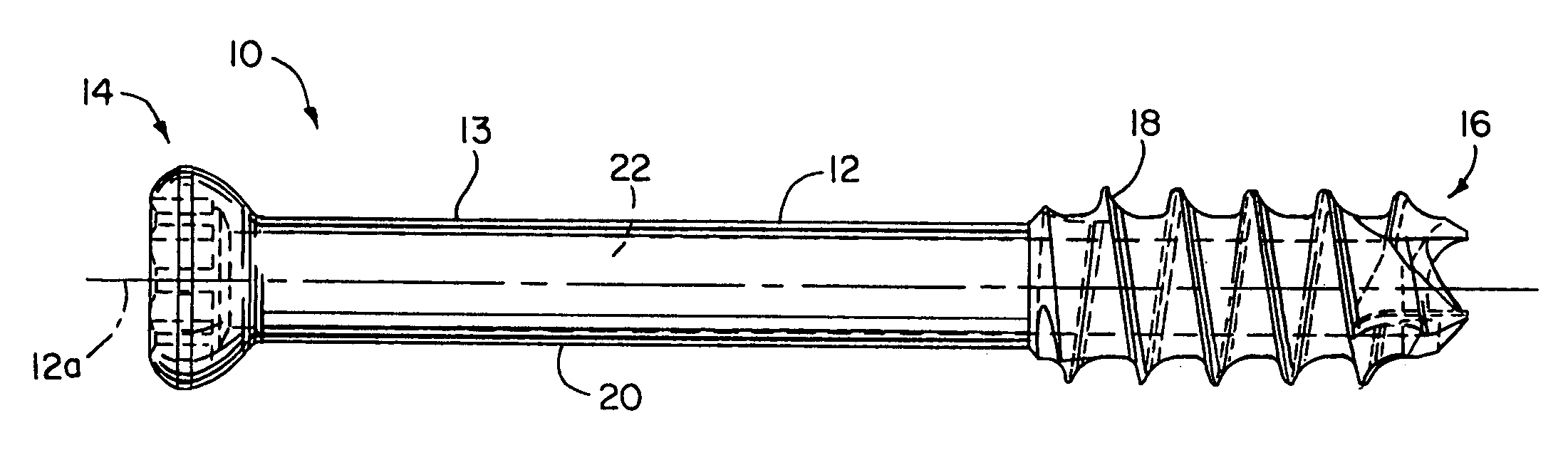
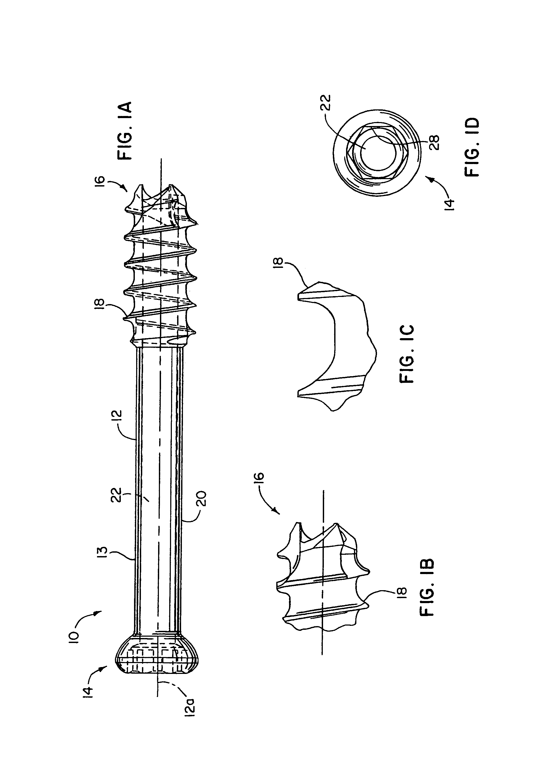
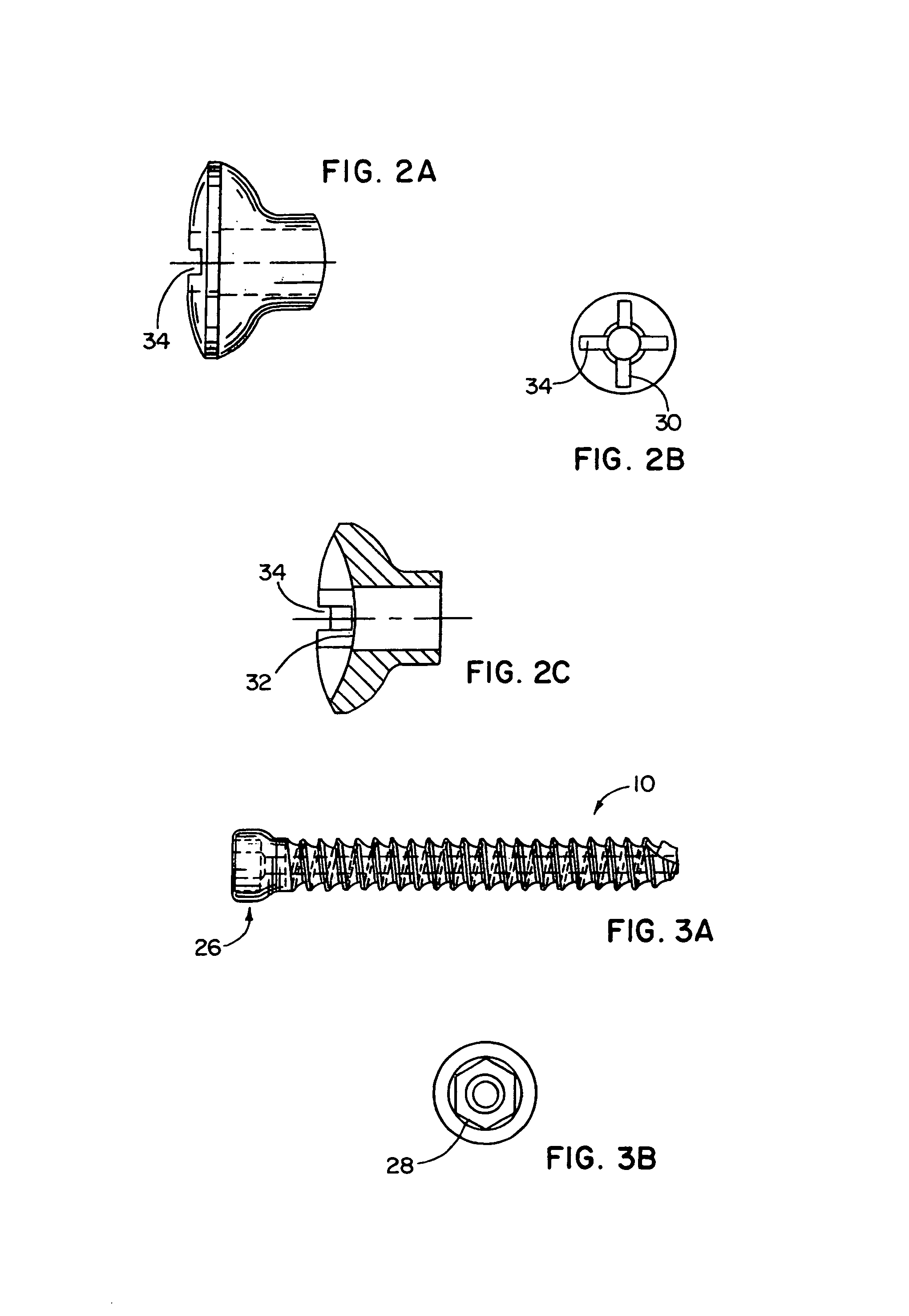
[0020]In FIGS. 1A–1D, a screw apparatus 10 in the form of bone screw 10a for being implanted into bone material is shown having one preferred configuration thereof. The bone screw apparatus 10 has an elongate shank 12 having proximal and distal ends 14 and 16, respectively. The shank 12 has external threads 18 formed along the shank 12 between the ends 14 and 16 thereof. As shown in the screw 10 of FIG. 1A, the screw shank 12 is only partially threaded from the distal self-tapping and self-drilling end 16 to approximately mid-way along the length of the shank 12 leaving an unthreaded section 20 thereof. Alternatively, the entire length of the shank 12 less screw head 26 can be threaded, as shown in FIG. 3A.

[0021]Referring to FIG. 4 and taking measurements for one of the listed screws 10, the thread outer or major diameter can be approximately 0.138 inches or 3.5 millimeters. As can be seen in FIGS. 1A and 1D, the shank 12 has a generally annular wall 13 including a throughbore or ca...


PUM


Abstract

A small cannulated bone screw is provided having an optimized combination of strength, cannula size and thread depth. A set of such strong and small size screws is also provided where the smallest sizes can have one performance ratio emphasized over another, and the larger sizes can have the emphasis reversed. In particular, the smallest screws optimize the combination of their strength and cannula size with the larger screws optimizing the combination of their strength and thread depth. In any event, each of the screws in the set has an optimized combination of strength, cannula size and thread depth throughout the full range of screw sizes in the set, e.g. 3.0 mm to 7.5 mm major diameters.

Description

[0001]This application claims the benefit of U.S. provisional patent application 60 / 356,221, filed Feb. 12, 2002.FIELD OF THE INVENTION[0002]The invention relates to bone screws and, more particularly, to small bone screws that are cannulated.BACKGROUND OF THE INVENTION[0003]Cannulated bone screws provided with an axial throughbore or cannula extending therethrough are known to allow use of guide wires that penetrate a bone at the desired implant site for the screw and guide the screw as it is being rotatably driven into the bone. One well known problem with bone screws is that as they start to go down in size in terms of the outer diameter of their threads, i.e., major diameter, the cannulas thereof likewise become very small so that only very thin guide wires can be used therewith. These thin guide wires are fairly flimsy and thus tend to bend and buckle, and walk on the surface of the bone when being inserted into the bone material. When this occurs, the location and / or angle of ...

Claims


Application Information

Patent Timeline
Patent Type & Authority Patents(United States)
IPC IPC(8): A61B17/86A61BA61B17/56
CPCA61B17/8625A61B17/864A61B17/866A61B17/8605A61B2019/301A61B2090/031
Inventor VLAHOS, JEFFSONGER, MATTHEW N.DAVENPORT, KENNETH
Owner PIONEER SURGICAL TECH INC
Why Eureka
Try Eureka