Bumper-beam for an automobile

Active Publication Date: 2007-11-01
FCA US
View PDF16 Cites 2 Cited by
  • Summary
  • Abstract
  • Description
  • Claims
  • Application Information

AI Technical Summary

Benefits of technology

[0006] An object of the present invention is to provide a bumper-beam with a higher capacity of force absorption by allowing a greater degree of deformation, i.e., better crush-space utilization.
[0008] Yet another object of the present invention is to provide a bumper-beam for an automobile, which is simpler in design and easier to assemble.
[0009] Yet another object of the present invention is to provide a bumper-beam that is made of cheap conventional materials rather than special expensive materials.
[0010] The present invention provides a bumper-beam for an automobile. The bumper-beam has a first set of surfaces and a second set of surfaces. The first set of surfaces is inclined at a pre-defined angle with respect to a pre-defined plane. The pre-defined angle ensures that the first set of surfaces buckle outward during an impact on the bumper-beam. The second set of surfaces has a plurality of slots, which facilitates the bumper-beam to crush during an impact.
[0011] The present invention also provides a safety system, which has a B-section bumper-beam and one or more rails. The B-section bumper-beam includes a first set of surfaces and a second set of surfaces. The first set of surfaces is inclined at a pre-defined angle with respect to a pre-defined plane. The pre-defined angle ensures that the first set of surfaces buckle outward during an impact on the B-section bumper-beam. The second set of surfaces has a plurality of slots which facilitates the B-section bumper-beam to crush during the impact. The B-section bumper-beam is connected to the one or more rails, which absorb the force generated due to the impact on the B-section bumper-beam.

Problems solved by technology

However, the bumper-beam may buckle in an undesirable manner, causing inadequate deformation, and therefore absorbing only a fraction of the force that it is capable of absorbing.
Hence, a large amount of force can be transmitted to the components, damaging them severely.
In the event of a rear collision, a damaged fuel tank and fuel leakage can cause fire and, therefore, can be fatal for the occupants of the automobile.
However, existing bumper-beams suffer from one or more of the following limitations.
They have complicated designs and are difficult to assemble.
Further, due to their complicated designs, their assembly requires various parts to be welded together.
In addition, they are expensive since they are made of special materials.
Moreover, they are not capable of withstanding high-magnitude forces generated due to an impact.

Method used


Image

  • Bumper-beam for an automobile
  • Bumper-beam for an automobile
  • Bumper-beam for an automobile

Examples


Embodiment Construction

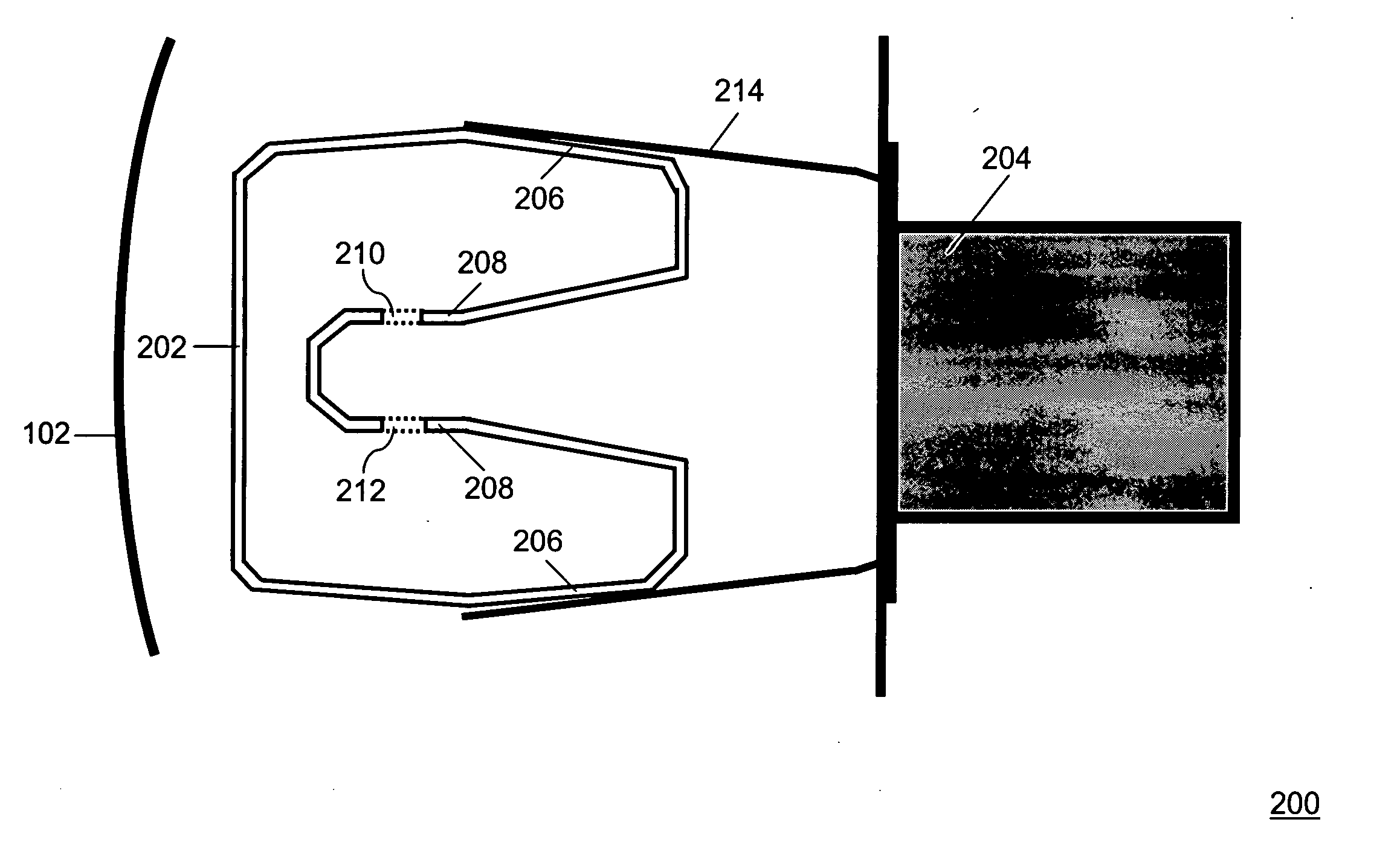
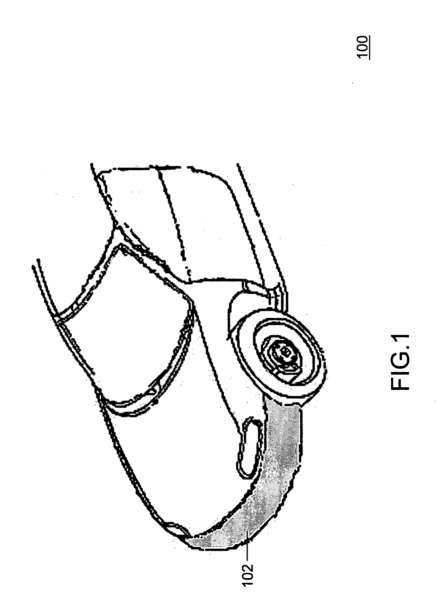
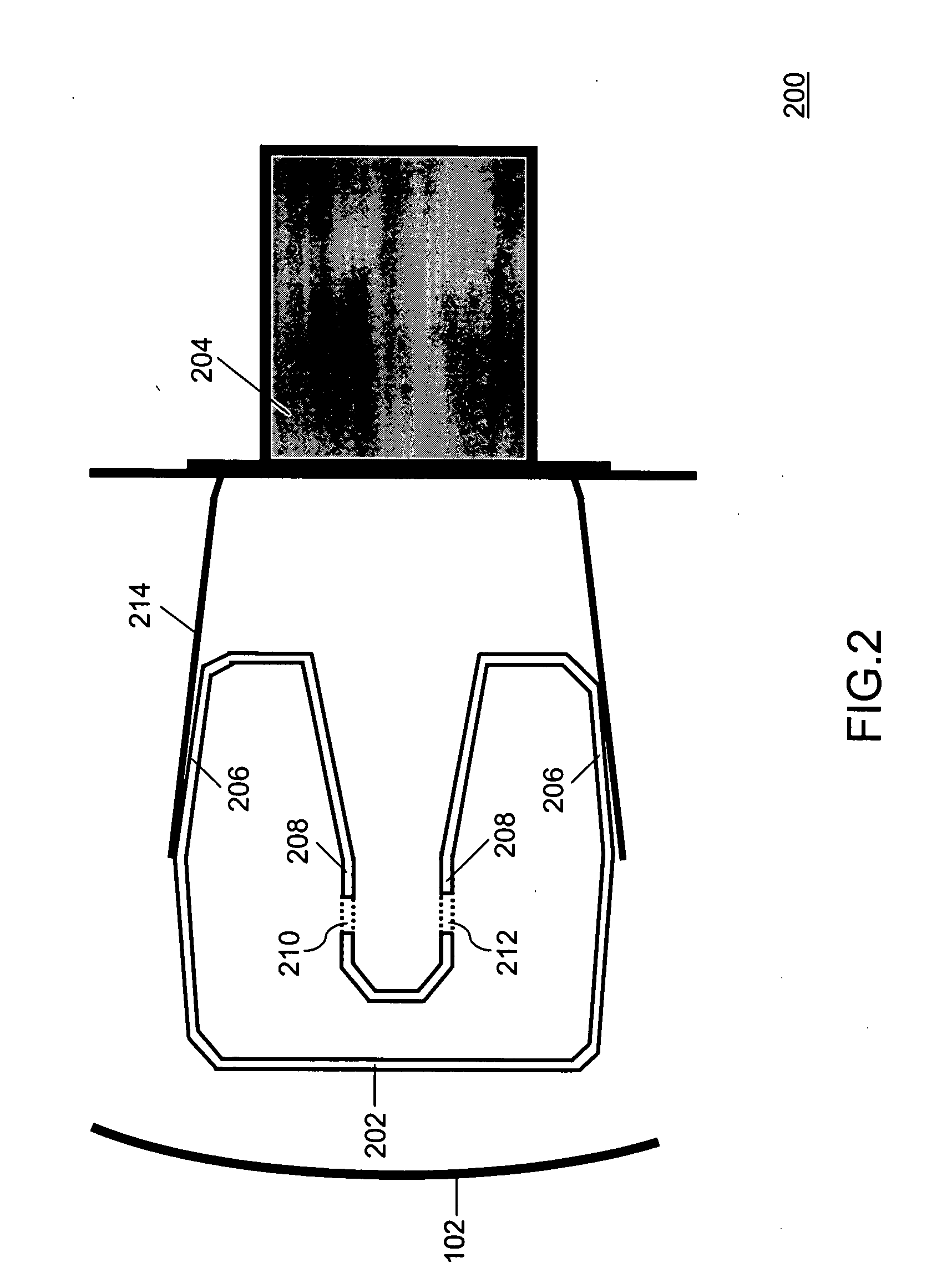
[0016] The present invention describes a bumper-beam for an automobile. The bumper-beam has a first set of surfaces and a second set of surfaces. The first set of surfaces is inclined at a pre-defined angle with respect to a pre-defined plane. The pre-defined angle ensures that the first set of surfaces buckle outward during an impact on the bumper-beam. A plurality of slots is provided on the second set of surfaces that facilitate the bumper-beam to crush during the impact on it.

[0017] The present invention also describes a safety-system for an automobile. This safety-system has a B-section bumper-beam and one or more rails. The B-section bumper-beam includes a first set of surfaces and a second set of surfaces. The first set of surfaces is inclined at a pre-defined angle with respect to a pre-defined plane. The pre-defined angle can lie in a range between 1 degree and 3 degrees. The pre-defined angle ensures that the first set of surfaces buckle outward during an impact on the B-...


PUM


Abstract

A bumper-beam for an automobile is disclosed, which has a first set of surfaces and a second set of surfaces. The first set of surfaces is inclined at a pre-defined angle with respect to a pre-defined plane. A plurality of slots is provided on the second set of surfaces of the bumper-beam, which facilitates the bumper-beam to crush during an impact.

Description

FIELD OF THE INVENTION [0001] The present invention generally relates to automobiles. More particularly, it relates to a bumper-beam for an automobile. BACKGROUND OF THE INVENTION [0002] Bumpers are attached to the front and the rear ends of automobiles such as cars, trucks and vans. They reduce damage to the automobile, specifically to the engine and the fuel tank, in the event of a front or rear collision. They can be made of a material such as plastic, acrylic and steel and improve the visual appearance of the automobile. The bumper envelops a bumper-beam, which is connected to the rails of the chassis that supports various components such as the engine and body of the automobile. The bumper-beam can absorb the force generated due to an impact on the bumper, such as during a front or rear collision, by deforming and buckling. This is referred to as crush-space utilization. Better crush-space utilization in the bumper-beam reduces the amount of force transmitted to the engine, the...

Claims


Application Information

Patent Timeline
IPC IPC(8): B60R19/34
CPCB60R19/34B60R19/18
Inventor NAICK, PRATAP ATCHUTHAKOKA, MADHUKEMP, RONALD SCOTTBEECHER, GREGORY A.
Owner FCA US
Why Eureka
Try Eureka