Overmolded Electrical Contact Array

a technology of electrical contact array and overmolded parts, which is applied in the manufacture of contact parts, coupling device details, coupling device connections, etc., can solve the problems of controlling the positioning and straightness of the mounting ends of electrical contacts

Active Publication Date: 2008-08-21
FCI AMERICAS TECH LLC
View PDF26 Cites 6 Cited by
  • Summary
  • Abstract
  • Description
  • Claims
  • Application Information

AI Technical Summary

Benefits of technology

[0005]The invention provides a connector that incorporates a tail-alignment housing that may control the position of the mounting, or “tail,” ends. The tail-alignment housing may also provide a structure that helps absorb the forces required for press fitting the connector to a printed circuit board (PCB). The tail-alignment housing may have a housing body and a plurality of tail supports extending from the housing body up and around the contact tails.

Problems solved by technology

Consequently, a relatively large number of individual insert molded leadframe assemblies (IMLAs) may be required to make such a connector.
Due to the number of separate IMLAs required to make such a connector, manufacturers have proposed insert molding the contacts into a plurality of horizontal arrays, or “rows.” With such connectors, however, there are problems with controlling the positioning and straightness of the mounting ends of the electrical contacts (i.e., the contact “tails”) in a cost-effective manner.

Method used


Image

  • Overmolded Electrical Contact Array
  • Overmolded Electrical Contact Array
  • Overmolded Electrical Contact Array

Examples


first embodiment

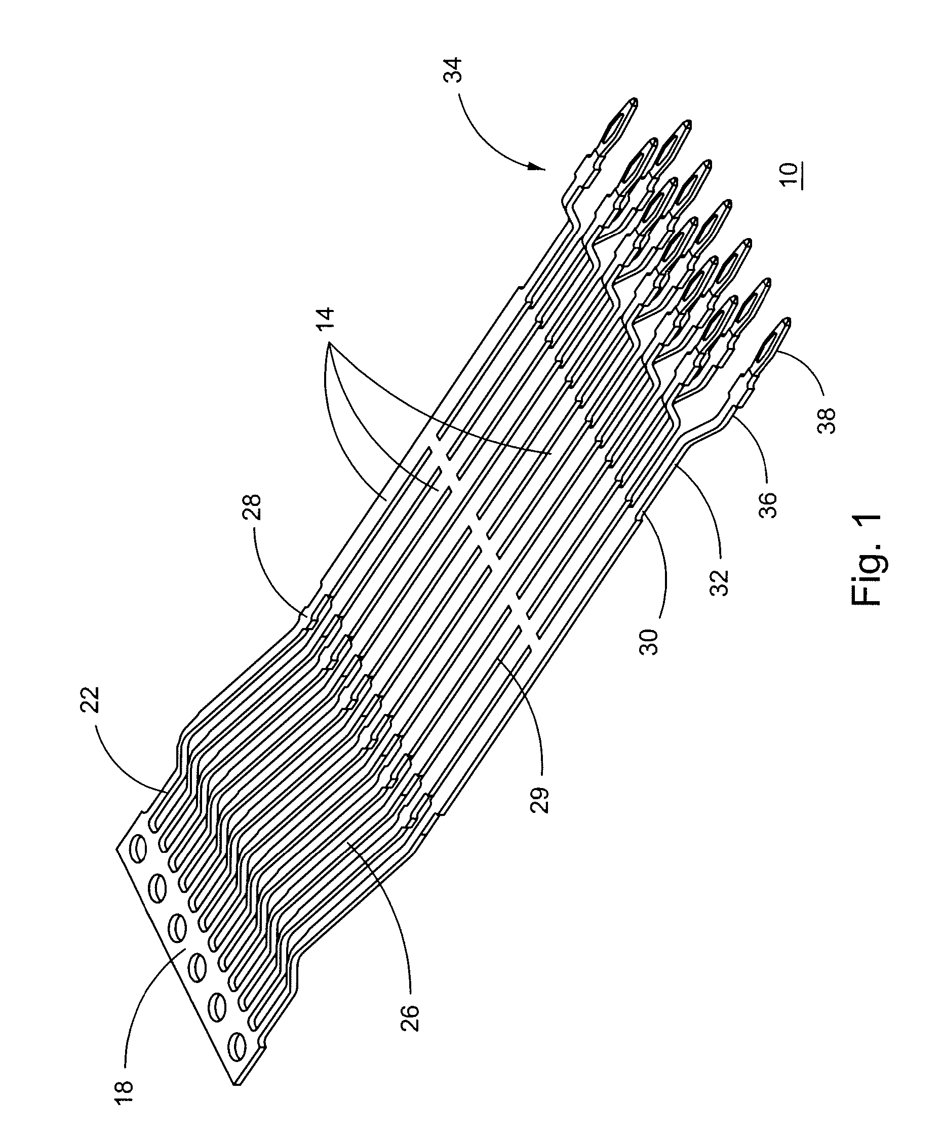
[0022]A first embodiment leadframe 10 of electrical contacts 14 may be stamped from a sheet of electrically conductive material, such as copper alloy, for example. FIG. 1 depicts the leadframe 10 of electrical contacts 14 attached to one another and to a carrier frame 18. Each contact 14 may include a mating end 22, a mating portion 26, a first housing portion 28, a lead portion 29, a second housing portion 30, a third housing portion 32, a mounting portion 34, and a mounting end 36. The lead portions 29 of the contacts may be attached to one another via “bridges” that remain after stamping. The mounting ends 36 of the contacts may each include a tail 38. The contacts 14 may be selectively gold plated.

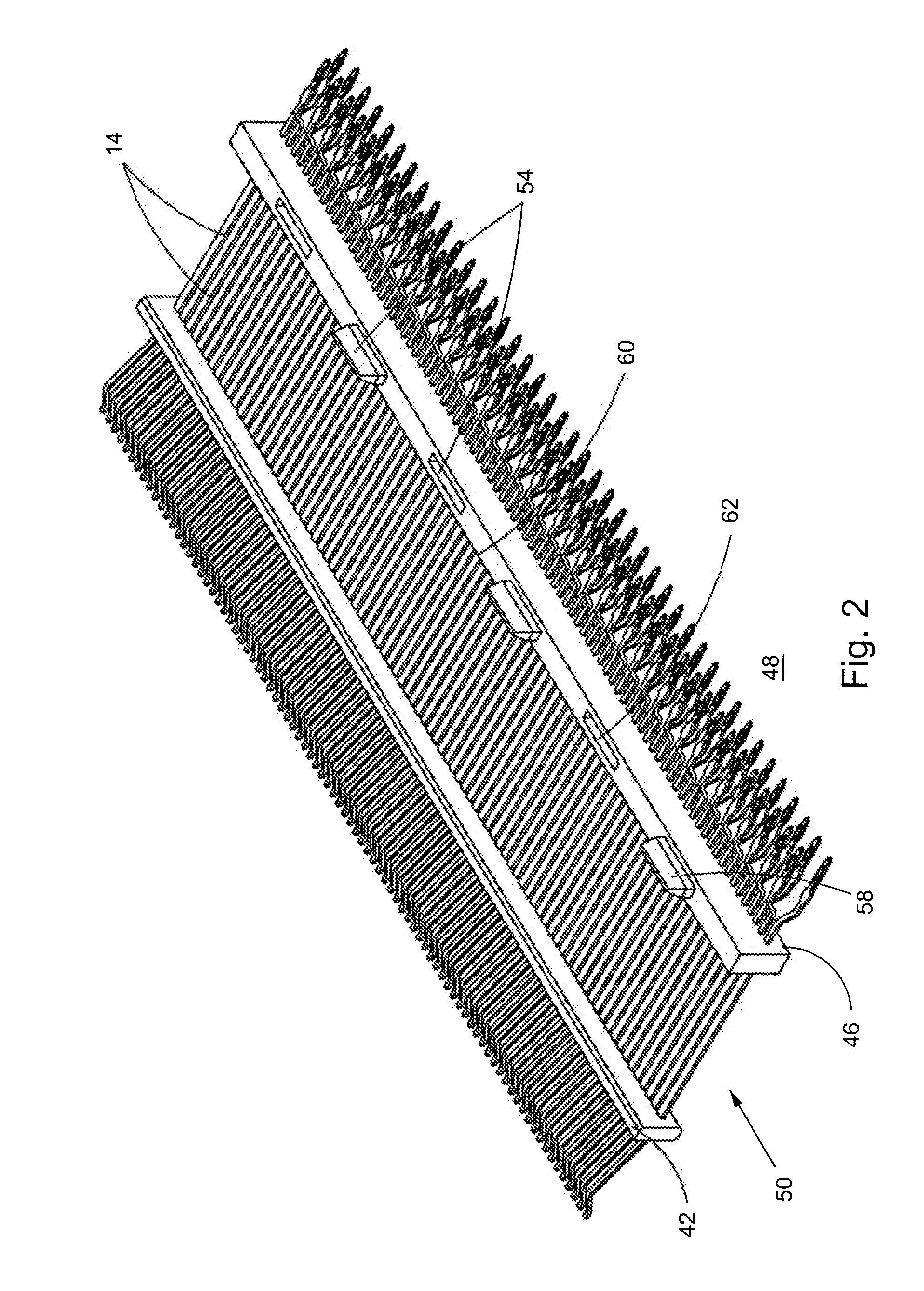
[0023]Once the leadframe 10 has been stamped, a first leadframe housing 42 may be overmolded onto the first housing portions 28 of the contacts 14. A second leadframe housing 46 may be overmolded onto the second housing portions 30 of the contacts. Each leadframe housing may be made of...

second embodiment

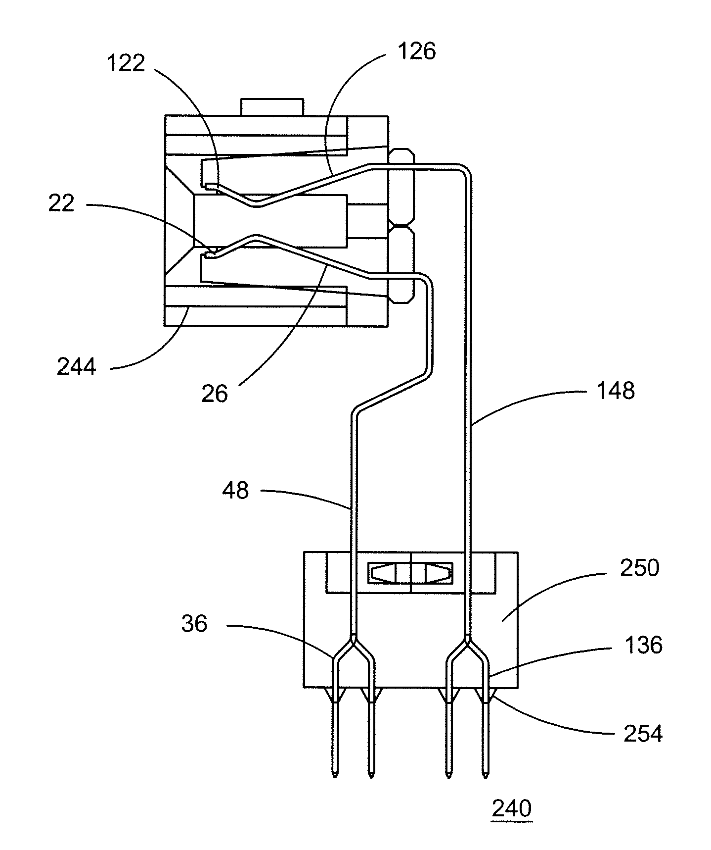
[0027]A second embodiment leadframe 110 of electrical contacts 114 may be stamped from a sheet of electrically conductive material, such as copper alloy, for example. FIG. 4, depicts the leadframe 110 of electrical contacts 114 attached to one another and to a carrier frame 118. Each contact 114 may include a mating end 122, a mating portion 126, a first housing portion 128, a lead portion 129, a second housing portion 130, a third housing portion 132, a mounting portion 134, and a mounting end 136. The lead portions 129 of the contacts 114 may be attached to one another via “bridges” that remain after stamping. The mounting ends 136 of the contacts 114 may each include a tail 138. The contacts 114 may be selectively gold plated.

[0028]After the leadframe 110 has been stamped, a first leadframe housing 142 may be overmolded onto the first housing portions 128 of the contacts 114. A second leadframe housing 146 may be overmolded onto the second housing portions 130 of the contacts 114...


PUM


Abstract

The invention provides a connector incorporating an overmolded housing that may control the position of the mounting ends of the connector and may provide a structure to help transfer the forces for press fit of the connector to the printed circuit board (PCB). Such a connector may include a first leadframe assembly having a plurality of contacts, a second leadframe assembly having a plurality of contacts, an edge card, and a tail alignment housing. Each contact may include a lead portion and a mounting end. The lead portions of the contacts may engage the edge card. The tail alignment housing may include a housing body and a plurality of tail supports extending from the housing body. The tail alignment housing may be overmolded onto at least a portion of the mounting ends.

Description

CROSS REFERENCE TO RELATED APPLICATION[0001]This application is related to application number (Attorney Docket No. FCI-3027 (C4060)), filed concurrently herewith.FIELD OF THE INVENTION[0002]The invention relates generally to electrical connectors. More particularly, the invention relates to connectors having tails.BACKGROUND OF THE INVENTION[0003]Advanced Mezzanine Cards are printed circuit boards (PCBs) that follow a specification of the PCI Industrial Computers Manufacturers Group (PICMG). PICMG AMC connectors may be used in accordance with such a specification. Typically, manufacturers of such connectors mold the contacts in a vertical (or “column”) direction. Accordingly, each column of contacts is molded into a separate leadframe assembly. In some such connectors, as many as 80 or more contact columns are required. Consequently, a relatively large number of individual insert molded leadframe assemblies (IMLAs) may be required to make such a connector.[0004]Due to the number of ...

Claims


Application Information

Patent Timeline
Patent Type & Authority Applications(United States)
IPC IPC(8): H01R12/00
CPCH01R12/585H01R12/716H01R43/16H01R13/405
Inventor SHUEY, JOSEPH B.JOHNSON, LEWISBRICKNER, DEREK L.GELOTTE, RYAN S.
Owner FCI AMERICAS TECH LLC
Why Eureka
Try Eureka