Water ballasted wave attenuator

a technology of water ballasted wave and attenuator, which is applied in the direction of buttress dams, construction, marine site engineering, etc., can solve the problems of affecting the safety of the waterway

Active Publication Date: 2010-03-18
0926084 B C
View PDF23 Cites 0 Cited by
  • Summary
  • Abstract
  • Description
  • Claims
  • Application Information

AI Technical Summary

Benefits of technology

[0011]A wave attenuator which utilizes water as a ballast below the water line is disclosed. Typically, the water ballasted wave attenuator is constructed of a reinforced concrete shell. The shell is typically constructed in an elongated box-like configuration. Polystyrene flotation is installed in the upper interior of the reinforced concrete shell. Water vents may be located in the lower region of the concrete shell or filler pipes in the upper portion and permit water to enter the lower interior of the concrete shell, below the polystyrene flotation. Once the wave attenuator is deployed in a body of water, water enters the lower interior of the reinforced concrete shell and enables the force of wave action to be fully or partially absorbed.

Problems solved by technology

Wave action generated by wind on large bodies of water has great force and can erode shorelines and cause damage to objects that are located in or adjacent the water bodies.
Conventional floating wave attenuators that are designed to deal with waves of high elevation, and substantial force must accordingly be of very heavy mass and are therefore cumbersome to transport and install.
Furthermore, the cost of a wave attenuator designed to deal with waves of high elevation, by having a large mass, is very expensive.
The alternate positioning of the modules in the configuration increases the turbulence of the waters flowing though the “brake” and in turn reduces their force and magnitude.

Method used


Image

  • Water ballasted wave attenuator
  • Water ballasted wave attenuator
  • Water ballasted wave attenuator

Examples


Embodiment Construction

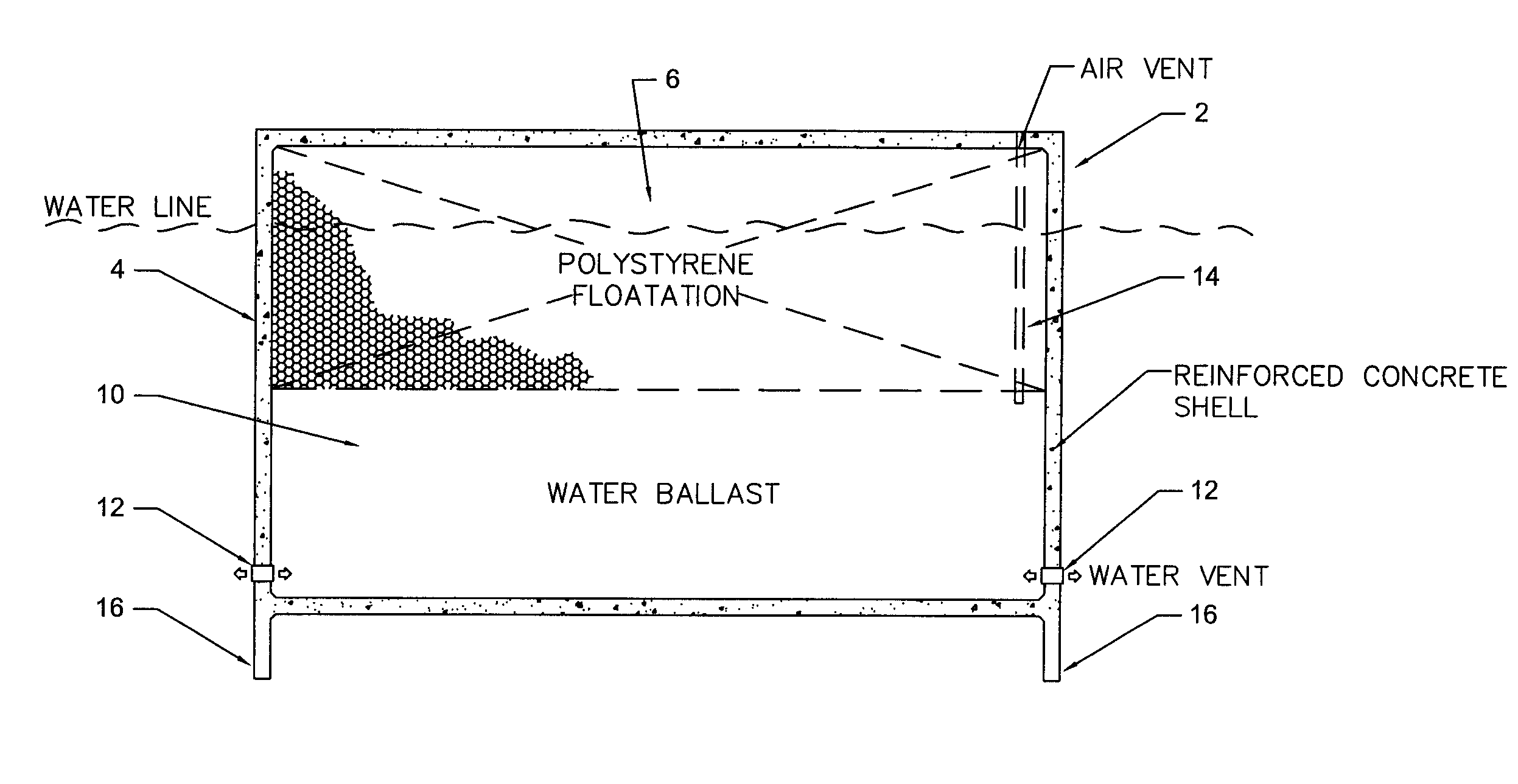
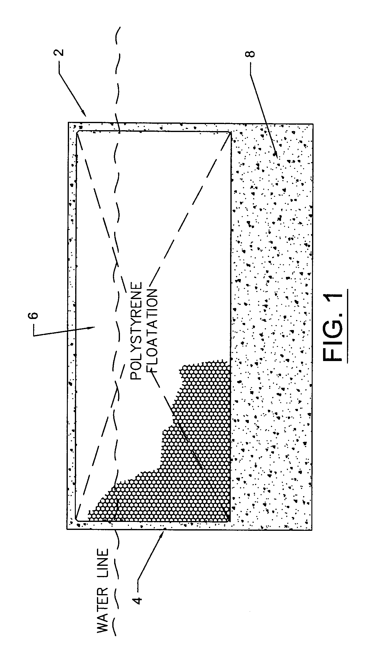
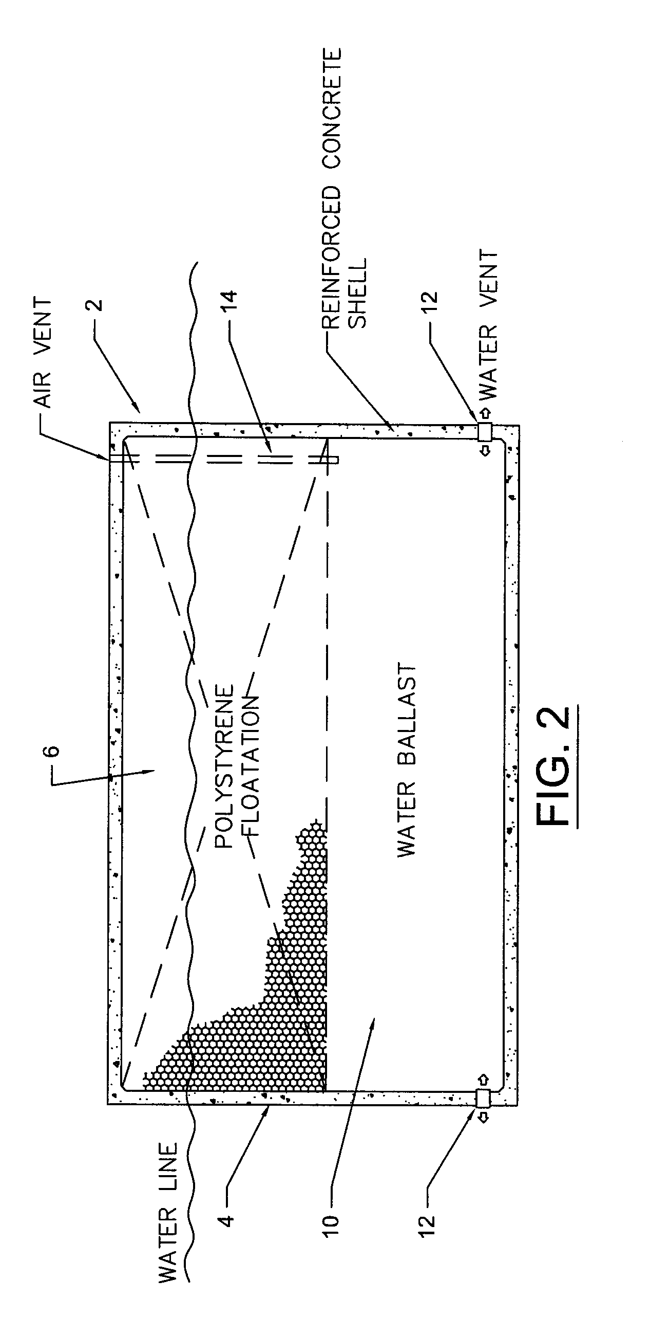
[0022]Water, when subjected to wave action, follows an elliptical motion. A wave's elliptical motion typically extends to a depth roughly half of the distance between wave crests. Wave attenuators of deeper depths are usually more effective in providing wave attenuation, than shallow wave attenuators. To the extent a wave's energy extends below a floating wave attenuator, a portion of the wave will travel under the structure and partially reform on the other side. Depending on the nature of the wave the important factors in floating water attenuation are the width and the mass of the attenuator.

[0023]Because the energy of a wave travels in an elliptical motion, the depth of a floating breakwater or attenuator is very important. If the bottom of the ellipse is greater than the depth of the wave attenuator, a portion of the wave's energy will travel under the wave attenuator and continue with reasonable force. Accordingly, the deeper the wave attenuator, the greater the wave dampening...


PUM


Abstract

This invention relates to a novel water ballasted wave attenuator that can be used to diminish or eliminate the impact of waves on shorelines or objects located in or on water bodies. A water ballasted wave attenuator comprising: (a) a hollow shell formed of reinforced concrete; (b) a flotation medium disposed in the upper region of the interior of the reinforced concrete shell (a); (c) an air chamber disposed below the flotation medium (b) in the lower region of the interior of the reinforced concrete shell; and, (d) at least one water vent located in the interior of the reinforced concrete shell (a), said vent connecting the interior of the shell with the exterior of the shell.

Description

REFERENCE TO RELATED APPLICATION[0001]This application claims Convention priority on U.S. provisional patent application Ser. No. 61 / 098,100, filed Sep. 18, 2008.FIELD OF THE INVENTION[0002]This invention relates to a novel water ballasted wave attenuator that can be used to diminish or eliminate the impact of waves on shorelines or objects located in or on water bodies.BACKGROUND OF THE INVENTION[0003]Wave action generated by wind on large bodies of water has great force and can erode shorelines and cause damage to objects that are located in or adjacent the water bodies. One of the techniques used to diminish or eliminate the force of the wave action on the object and protect the object is to deploy a floating wave attenuator on the wave side of the object. The floating wave attenuator absorbs a percentage of the force of the wave, thereby protecting the object on the lee side of the wave attenuator.[0004]As a general physical rule, the height of the wave is proportional to the fo...

Claims


Application Information

Patent Timeline
Patent Type & Authority Applications(United States)
IPC IPC(8): E02B3/04
CPCE02B3/062Y02A10/11
Inventor WITTENBERG, DANIELMCCALLUM, LOCKHART GORDONFIELD, ROBERT WILLIAM RICHARD
Owner 0926084 B C
Why Eureka
Try Eureka