Measuring a Tensile Force

Active Publication Date: 2008-05-22
TEXMAG GMBH VERTRIEBS
View PDF26 Cites 11 Cited by
  • Summary
  • Abstract
  • Description
  • Claims
  • Application Information

AI Technical Summary

Benefits of technology

[0005]An object of the present invention is to further develop an apparatus to measure a tensile force within one or more material webs or material strands, said

Problems solved by technology

In addition, it is difficult to mount the tensi

Method used


Image

  • Measuring a Tensile Force
  • Measuring a Tensile Force
  • Measuring a Tensile Force

Examples


Example

DETAILED DESCRIPTION OF THE DRAWINGS

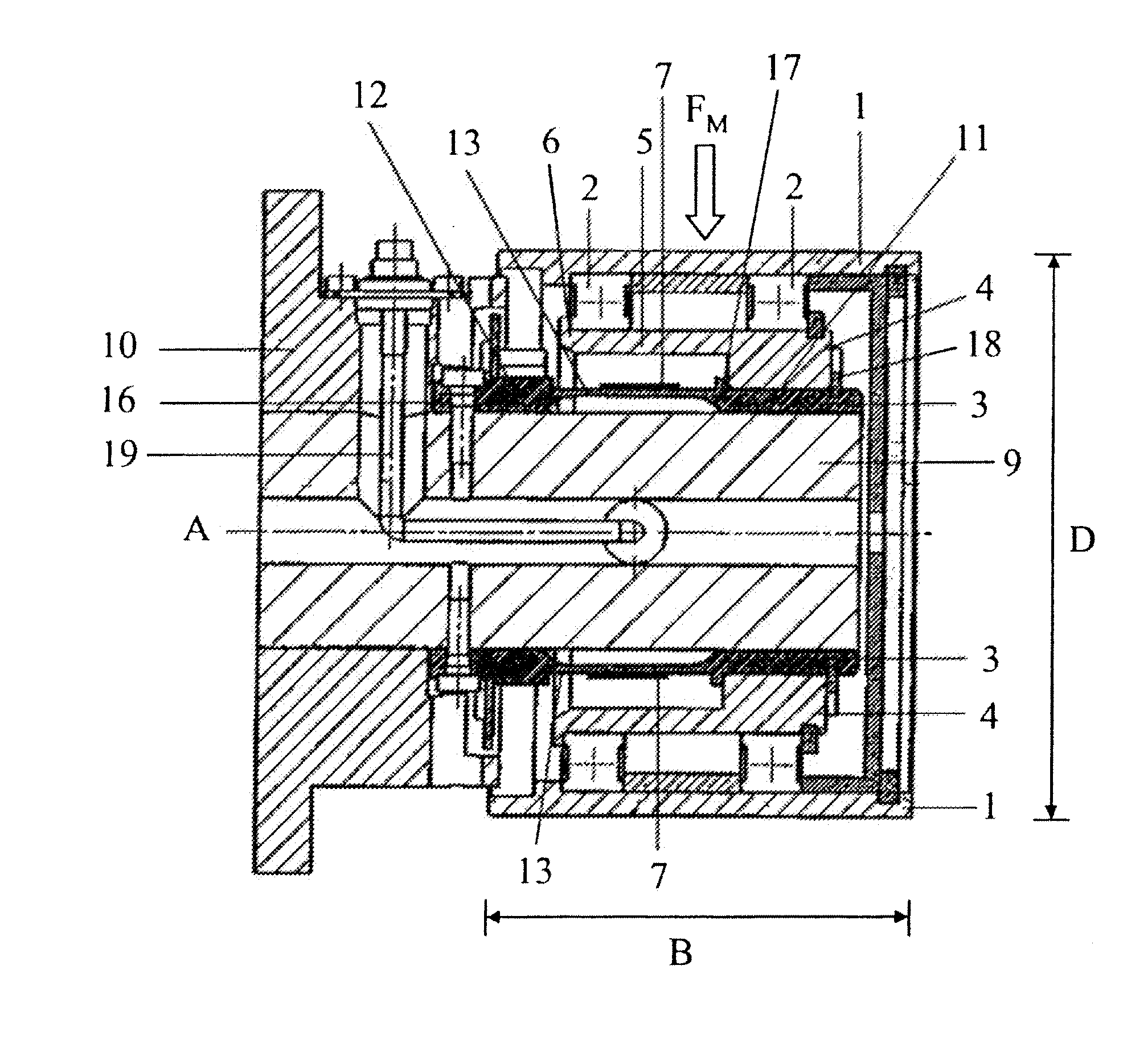
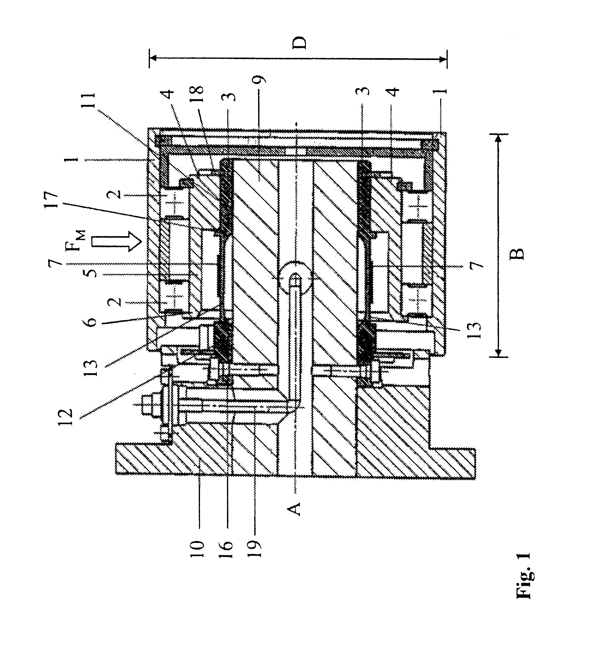
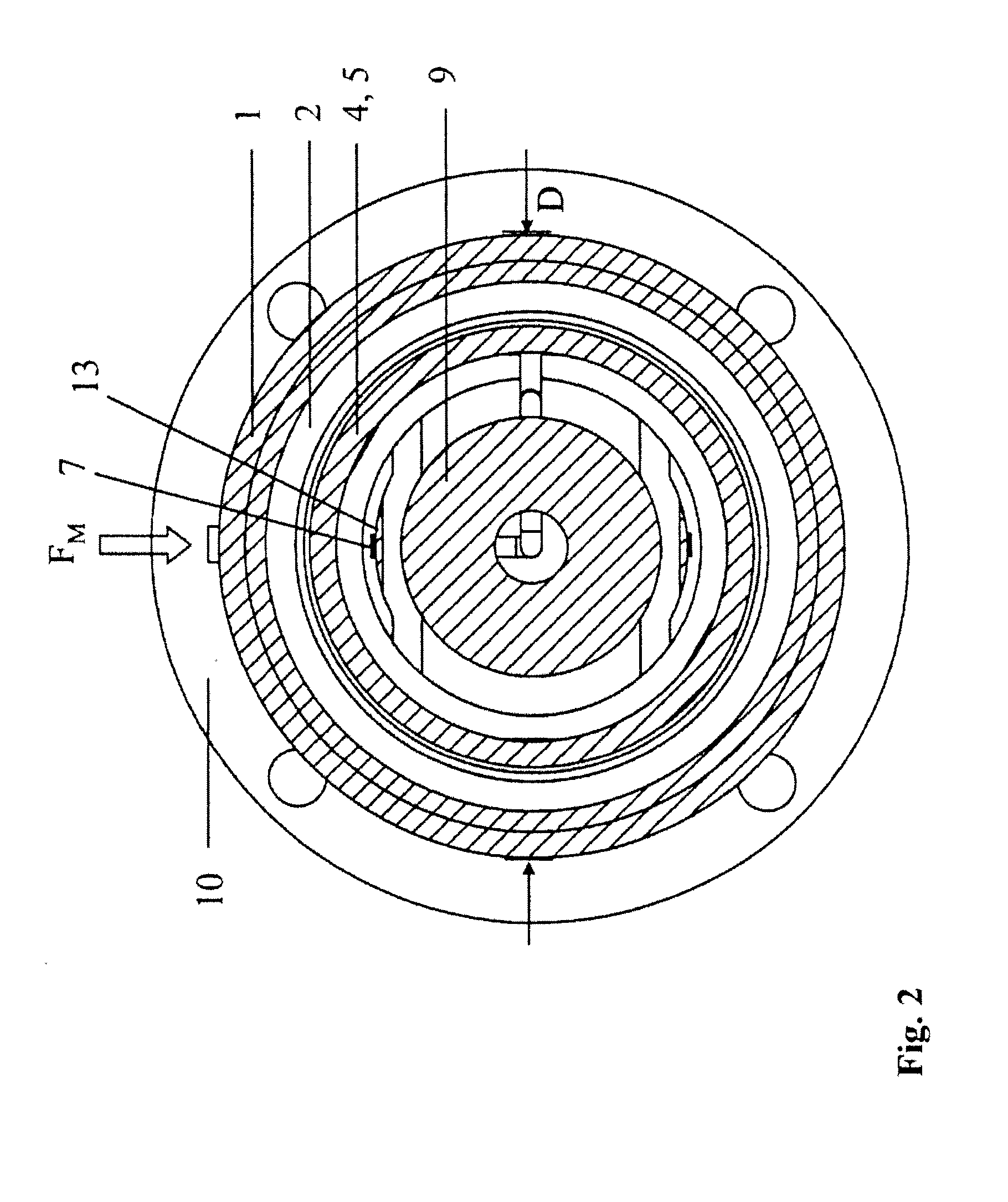
[0032]FIG. 1 and FIG. 2 show a longitudinal section and a cross section of the apparatus according to an embodiment of the present invention. Such an apparatus is used to measure a tensile force within a material web or a material strand or a force FM that is exerted by the material web or material strand on the apparatus. Alternatively, a transfer force FÜ can be measured that results from the force FM exerted by the material web or material strand on the apparatus. Such apparatuses are used in particular in systems to convey and / or process material webs or material strands.

[0033]The apparatus according to FIG. 1 and FIG. 2 comprises a roller barrel 1, two bearings 2 on which the roller barrel is rotatably mounted, and a first force transfer element 3 to transfer the transmitted force FÜ. The first force transfer element 3 is designed to react to the transmitted force FÜ in a direction parallel to the axis of rotation A of the roller barrel 1 wit...


PUM


Abstract

The invention pertains to an apparatus to measure a tensile force within at least one material web or at least one material strand or a corresponding force (FM) that is exerted on the apparatus, or a transmitted force (FÜ) resulting therefrom. The apparatus comprises at least one roller barrel (1), at least one bearing (2) to rotatably mount the roller barrel (1), at least one first force transfer element (3) to transfer the transmitted force (FÜ), said element designed to react to this transmitted force (FÜ) with an elongation, compression or other shape change in a direction parallel to the axis of rotation (A) of the at least one roller barrel (1), and at least one sensor (7) that is connected to the at least one first force transfer element (1). According to one aspect of the invention, the apparatus further comprises at least one second force transfer element (4) that extends inside the associated roller barrel (1) and that is connected to the first force transfer element (3). Through this design, an improved absorption of force is facilitated as well as a force measurement apparatus of minimal width (B).

Description

TECHNICAL AREA[0001]The present invention pertains to an apparatus to measure a tensile force within a material web or a material strand. The present invention also involves a method that uses an apparatus to measure a tensile force within a material web or a material strand, as well as a system that comprises such an apparatus.PRIOR ART[0002]There are known apparatuses in the prior art to measure a tensile force within a material web or a material strand.[0003]EP 0 621 469 B1 discloses a tensile force measuring device to measure tensile forces in continuously running materials, in particular material webs or threads. This tensile force measuring device is located on a fixed clamped shaft axis and comprises a clamping area with a massive closed ring with a penetration hole, and a bearing area that can move freely in relation to the shaft in the direction of force. The clamping area and bearing area are connected together by a flexible spring.[0004]Concerning the massive, closed ring...

Claims


Application Information

Patent Timeline
IPC IPC(8): G01L5/10
CPCG01L5/045G01L5/0019
Inventor LOENNER, WOLFGANGROESSLE, THOMASPALATZKY, ROLAND
Owner TEXMAG GMBH VERTRIEBS
Why Eureka
Try Eureka