Rheometer torque calibration fixture

a torque calibration and rheometer technology, applied in the field of rheometer calibration, can solve the problems of increasing the cost of operation, affecting the accuracy of calibration and hence the constancy of the instrument, and prone to both operator errors and systematic errors of calibration methods that use lines, pulleys or strain gauges

a torque calibration and rheometer technology, applied in the field of rheometer calibration, can solve the problems of increasing the cost of operation, affecting the accuracy of calibration and hence the constancy of the instrument, and prone to both operator errors and systematic errors of calibration methods that use lines, pulleys or strain gauges

US20070295055A1Inactive Publication Date: 2007-12-27WATERS TECH CORP

Image

  • Rheometer torque calibration fixture
  • Rheometer torque calibration fixture
  • Rheometer torque calibration fixture

Examples


Embodiment Construction

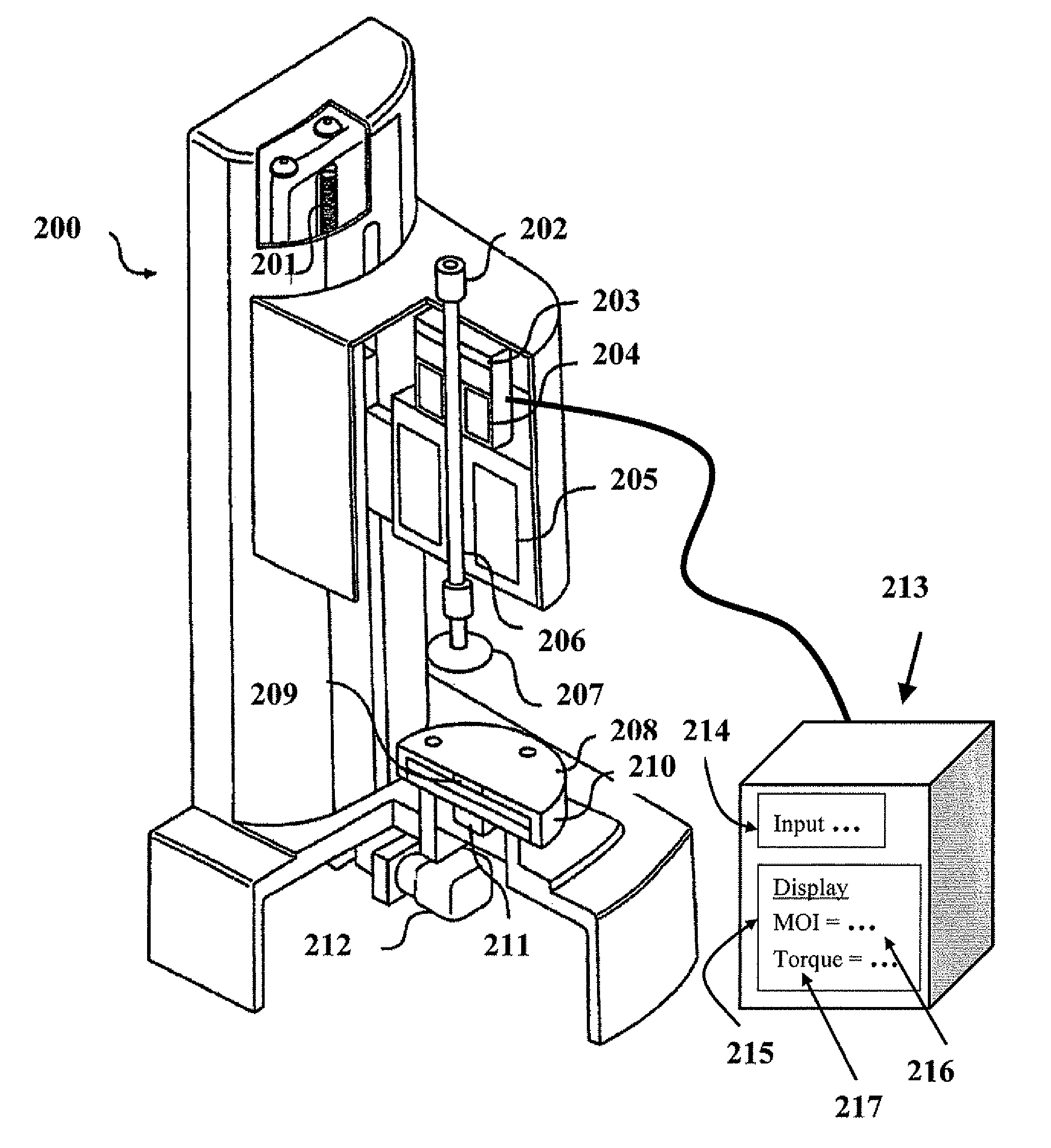
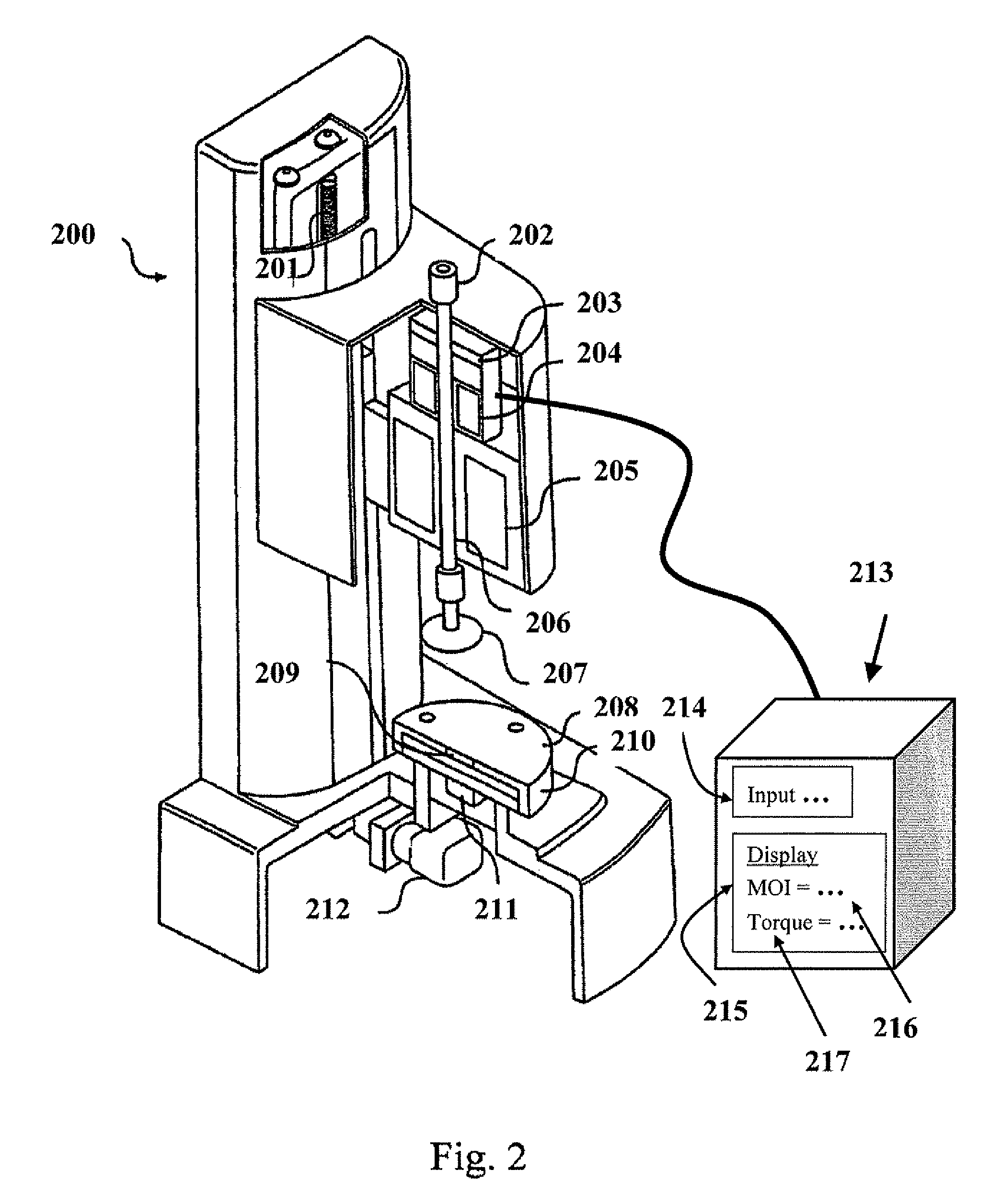
[0024]FIG. 2 is a schematic perspective view of a rotary rheometer 200, showing lead screw 201, draw rod 202, optical encoder 203, air bearing 204, drag cup motor 205, drive shaft 206, measuring object 207, surface 208, temperature sensor 209, heating / cooling assembly 210, normal force transducer 211, and auto gap set motor and encoder 212. The drag cup motor 205 contains a current in its coils to generate and apply a torque to the drive shaft 206. The torque in the drive shaft 206, in turn, applies torque to the measuring object 207. An exemplary embodiment of the invention has a computer system 213, which is herein used to mean any assembly of at least one type of device that is programmable or capable of receiving inputted data, storing data, performing calculations, or displaying data. The computer system 213 may be equipped with an algorithm to calculate different rheological properties such as the MOI and the viscosity. The computer system 213 may comprise a display device 215...


PUM


Abstract

A method of calibrating the torque outputs of a rheometer by using a calibrating object with a certified moment of inertia, measuring the moment of inertia of the calibrating object using the rheometer, and calculating the torque adjustment factor by dividing the certified moment of inertia value by the measured moment of inertia value. The torque adjustment factor is applied to correct subsequent measurements of rheological properties conducted using the rheometer. The torque adjustment factor may be double-checked for reproducibility by measuring the moment of inertia of the calibrating object, correcting it with the torque adjustment factor, and comparing it with its certified moment of inertia value.

Description

[0001] This application claims the benefit of U.S. Provisional Application No. 60,815,566, filed Jun. 22, 2006, which is herein incorporated by reference in its entirety.BACKGROUND [0002] 1. Field of the Invention [0003] The present invention relates generally to the calibration of rheometers, which are used to characterize materials by measuring the materials' viscosity, elasticity, shear thinning, yield stress, compliance and / or other material properties. More particularly, the invention relates to calibrating the torque output of a rheometer. [0004] 2. Background of the Invention [0005] Rheometers, viscometers or viscosimeters are typically used to measure fluid or other properties of materials, such as their viscosity, compliance, and modulus, by rotating, deflecting or oscillating a measuring geometry in a material, either by applying a torque and measuring the resultant velocity or displacement, or by applying a velocity or displacement and measuring the resultant torque. The ...

Claims


Application Information

Patent Timeline
27 Dec 2007
Publication
US20070295055A1
IPC
G01N11/14; G01L5/00; G01L25/00; G01M1/10
CPC
G01N11/14
Inventors
DOE, NIGEL