Organic light-emitting device

a light-emitting device and organic technology, applied in the direction of organic semiconductor devices, discharge tubes/lamp details, discharge tubes luminescnet screens, etc., can solve the problems of reduced electron injection efficiency, increased voltage at which a light-emitting element is driven, and difficult to improve light extraction efficiency by controlling the thickness of the electron injection layer, etc., to achieve the reduction of emission efficiency, the effect of increasing the driving voltage of the element and improving the light extraction efficiency of organic light-emi

Inactive Publication Date: 2007-12-27
CANON KK
View PDF6 Cites 38 Cited by
  • Summary
  • Abstract
  • Description
  • Claims
  • Application Information

AI Technical Summary

Benefits of technology

[0013]In the present invention, each light extraction efficiency of organic light-emitting elements for respective colors can be improved without an increase in driving voltage of the element and a reduction in emission efficiency by controlling the thickness of the electron injection layer of the element and the concentration at which the electron injection layer is doped with an electron injection material.

Problems solved by technology

In a conventional constitution using a single layer of an electron injection material such as lithium fluoride (LiF) or potassium fluoride (KF) as an electron injection layer, a thickness capable of electron injection is extremely small, specifically, 5 to 10 Å, so that it has been difficult to improve light extraction efficiency by controlling the thickness of the electron injection layer.
However, extensive studies made by the inventors of the present invention have shown that, even in the case of an electron injection layer obtained by doping an organic compound with an electron injection material, electron injection efficiency reduces with decreasing thickness of the layer, with the result that the voltage at which a light-emitting element is driven increases.
Further, a reduction in emission efficiency has occurred as a result of the loss of the optimum carrier balance in some cases.
For example, there arises the following problem: when the thickness of the electron injection layer of an organic light-emitting element capable of emitting blue light having a short wavelength is reduced for improving the light extraction efficiency of the element, an increase in driving voltage of the element and a reduction in emission efficiency occurs.

Method used


Image

  • Organic light-emitting device
  • Organic light-emitting device
  • Organic light-emitting device

Examples


example 1

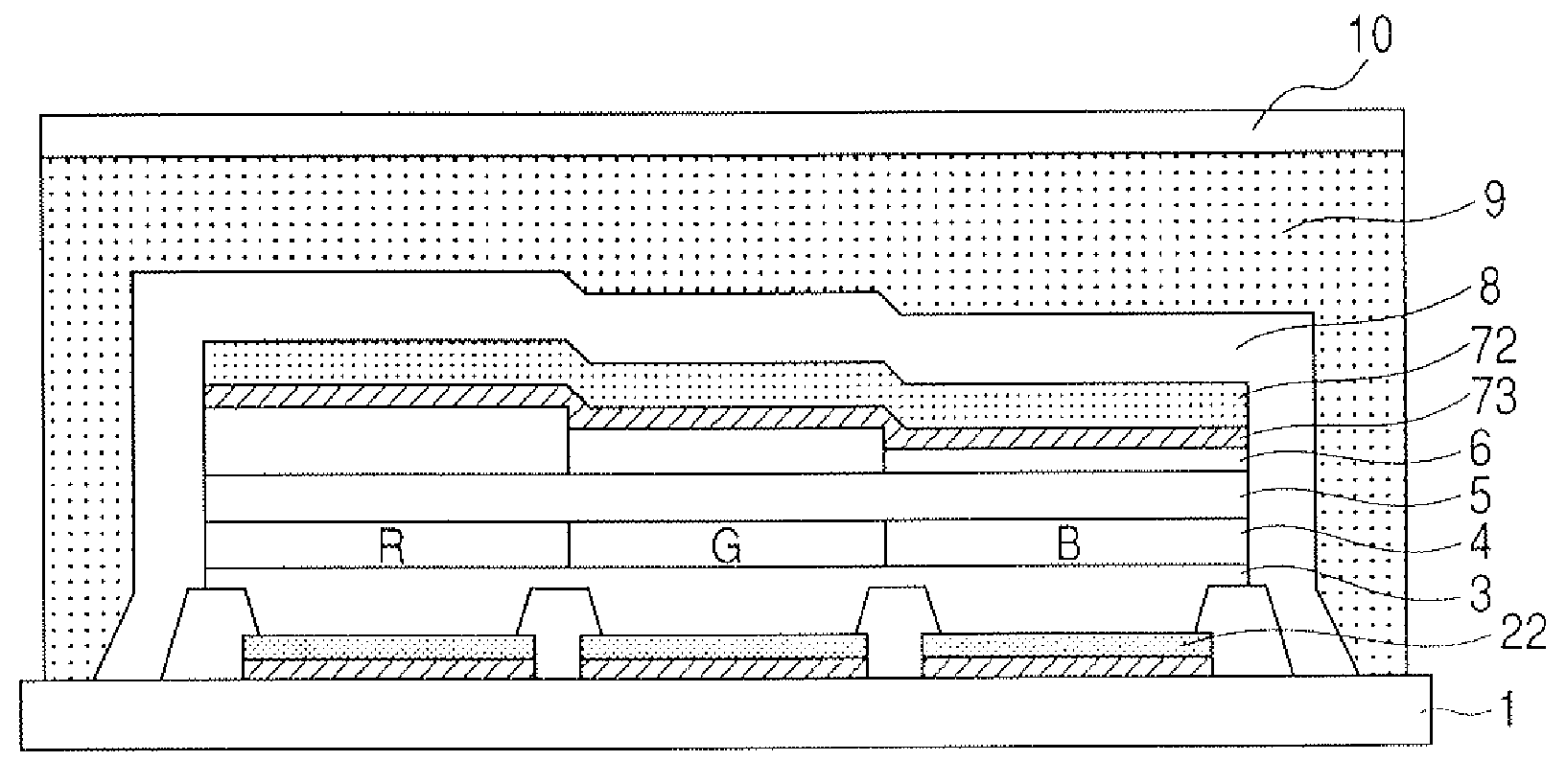
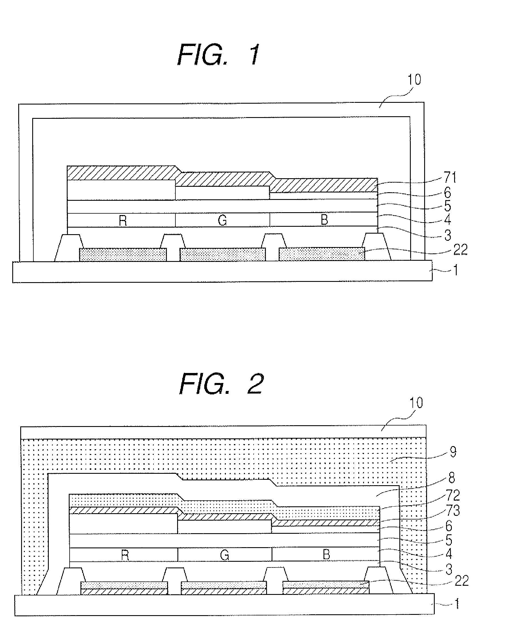
[0043]An organic light-emitting device having a structure shown in FIG. 1 and including organic light-emitting elements for emitting three color lights of red (R), green (G) and blue (B) are produced by the following method. The chemical formulae of organic compounds to be used are shown below in this example, and Table 1 shows the thicknesses of respective layers and electrodes in red, green and blue light-emitting elements which are abbreviated as “Red”, “Green” and “Blue” in Tables 1 to 10.

TABLE 1RedGreenBlueCathode150 nm(A1)Electron injection30 nm20 nm10 nmlayerElectron transport 10 nmlayerLight-emitting30 nm30 nm30 nmlayerHole transport 40 nmlayerAnode120 nm(ITO)

[0044]The light-emitting device according to this example is the so-called bottom emission type light-emitting device in which light is extracted from the side of the transparent anode 22 as an electrode on the side of the substrate 1. Then, the light-emitting device improves light extraction efficiency by adjusting an ...

example 2

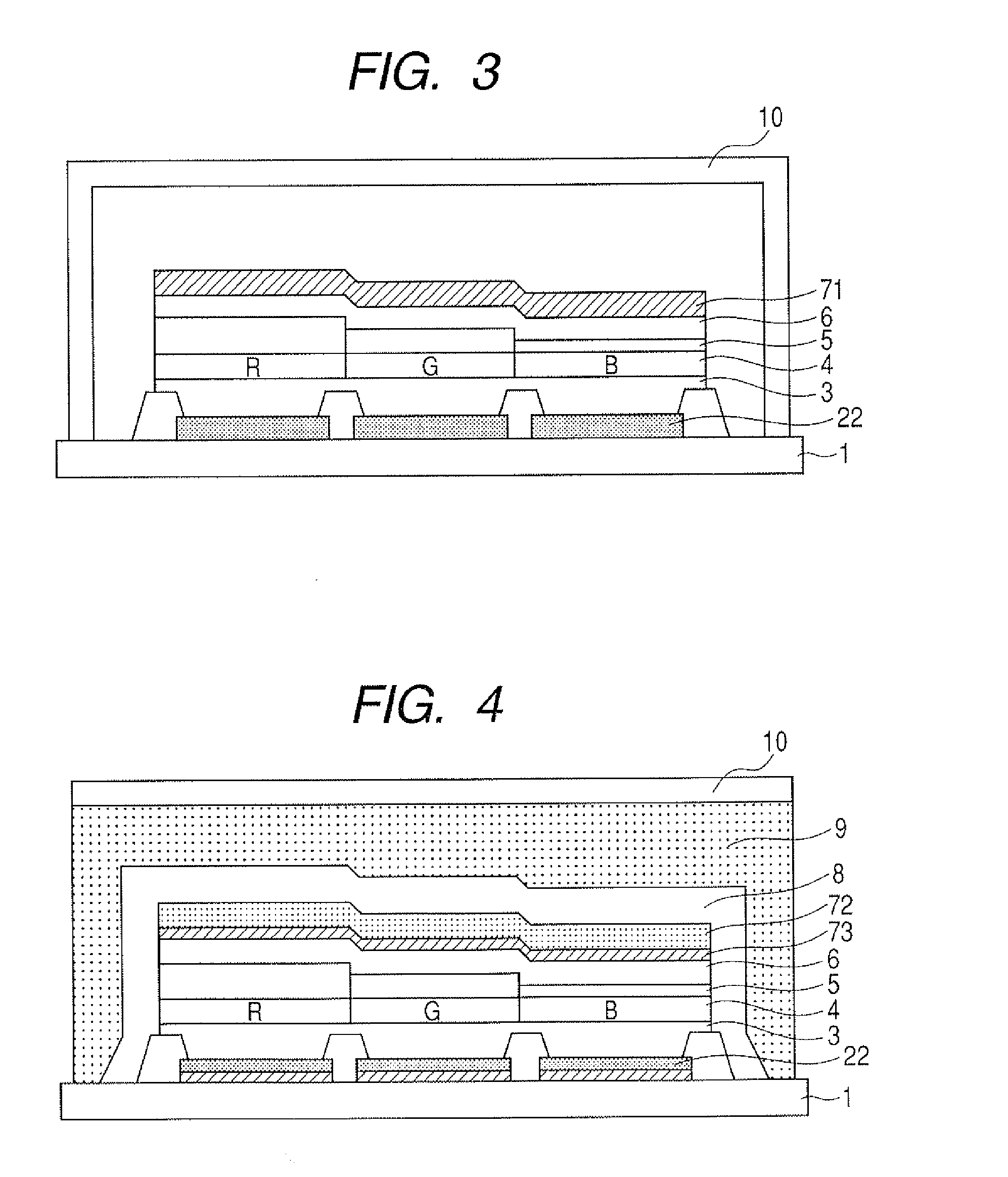
[0061]An organic light-emitting device having a structure shown in FIG. 2 and capable of emitting three lights of R, G and B is produced by the following method. Table 6 shows the thickness of the respective layers and electrodes in R, G and B light-emitting elements.

TABLE 6RedGreenBluePV film1200 nm Cathode (IZO)60 nmSemi-transparent cathode15 nm(Ag)Electron injection layer40 nm30 nm20 nmElectron transport layer10 nmLight-emitting layer40 nm30 nm30 nmHole transport layer20 nmTransparent cathode (IZO)20 nmReflective anode (AgAuSn)100 nm 

[0062]The light-emitting device according to this example is the so-called top emission type light-emitting device in which light is extracted from the side of the semi-transparent cathode 73 as an electrode on a side opposite to the substrate side. Then, the light extraction efficiency of the light-emitting device is improved by adjusting an optical distance between an interface of semi-transparent 73 and the electron injection layer 6 and an interf...


PUM


Abstract

Provided is an organic light-emitting device in which light extraction efficiency for the luminescent color of each of organic light-emitting elements can be improved without an increase in driving voltage and a reduction in emission efficiency. The organic light-emitting elements for respective luminescent colors are different from each other in thickness of an electron injection layer, and the concentration of a metal or a metal compound in an electron injection layer is adapted to increase as the thickness of the electron injection layer decreases.

Description

BACKGROUND OF THE INVENTION[0001]1. Field of the Invention[0002]The present invention relates to an organic light-emitting device to be used in, for example, a flat panel display, a projection display, or a printer.[0003]2. Description of the Related Art[0004]Organic light-emitting elements (organic EL elements or organic electroluminescence elements) have been actively researched and developed these days. It has been known that an aluminum-lithium alloy or a magnesium-silver alloy is used in the cathode of any such organic light-emitting element in order that electron injection efficiency may be improved. It has been also known that an extremely thin layer (having a thickness of 5 to 10 Å) of a dielectric substance such as lithium, lithium fluoride, magnesium oxide, or potassium fluoride is inserted into an electron injection layer in contact with the cathode.[0005]Japanese Patent Application Laid-Open No. H10-270171 discloses a constitution in which an electron injection layer (ha...

Claims


Application Information

Patent Timeline
Patent Type & Authority Applications(United States)
IPC IPC(8): H01J1/62
CPCH01L27/3211H01L51/5052H01L51/5237H05B33/10H01L51/5265H01L2251/558H01L51/5262H10K59/35H10K50/165H10K50/171H10K50/8426H10K50/852H10K50/85H10K50/844H10K2102/351
Inventor MATSUDA, YOJIRO
Owner CANON KK
Why Eureka
Try Eureka