Voltage regulator

a voltage regulator and voltage terminal technology, applied in the field of voltage regulators, can solve the problems of reducing the current for charging the external capacitor connected with the output voltage terminal, and prolonging the rise time of the output voltage of the voltage regulator, so as to reduce the rise time of the output voltage and limit the current of the output circui

Active Publication Date: 2008-02-28
ABLIC INC
View PDF5 Cites 1 Cited by
  • Summary
  • Abstract
  • Description
  • Claims
  • Application Information

AI Technical Summary

Benefits of technology

[0013] According to the voltage regulator of the present invention, a first output current limit value of the first output current limiting circuit is lower than a second output current limit value of the second output current limiting circuit and the detecting circuit enables operation of the first output current limiting circuit only when a rise speed of the input voltage is fast.
[0014] Thus, according to the voltage regulator of the present invention, a rush current of the output circuit can be limited and a rise time of the output voltage can be shortened.

Problems solved by technology

Therefore, because of unnecessary limitation given to the drain current, a current for charging the external capacitor connected with the output voltage terminal reduces, with the result that a rise time of the output voltage of the voltage regulator becomes longer.

Method used


Image

  • Voltage regulator
  • Voltage regulator
  • Voltage regulator

Examples


embodiment 1

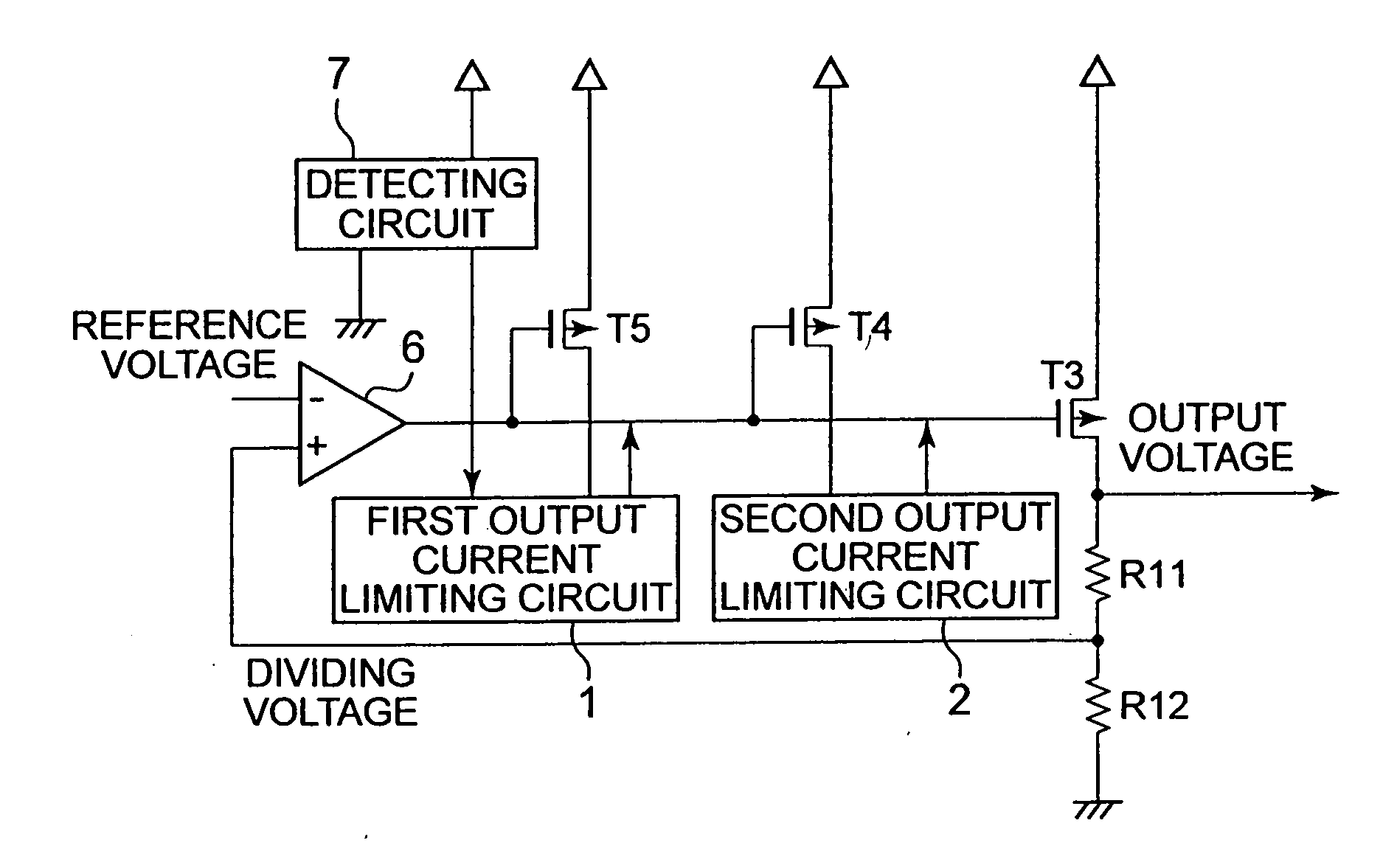
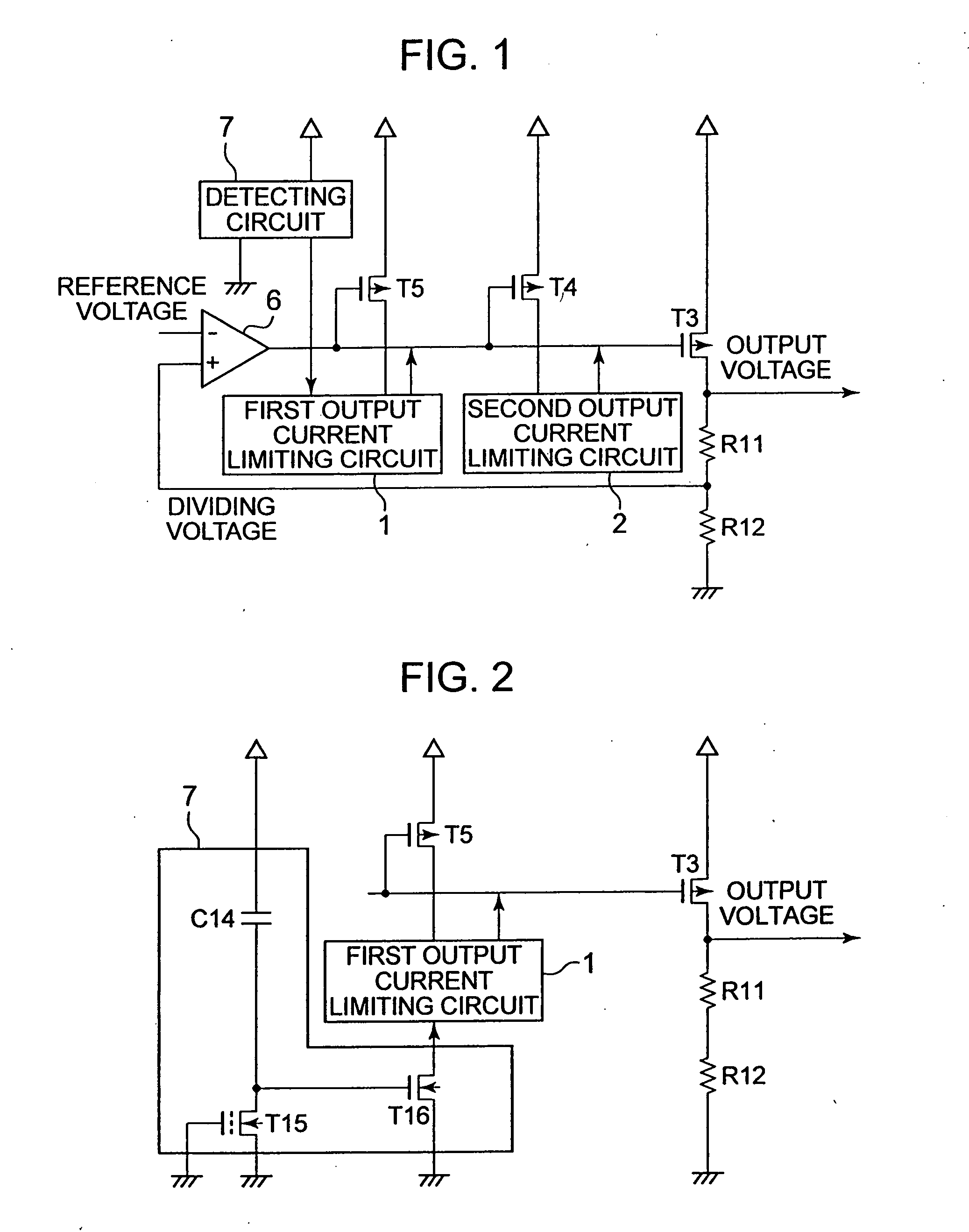
[0020]FIG. 1 is a block diagram showing a voltage regulator according to Embodiment 1.

[0021] The voltage regulator according to Embodiment 1 includes an amplifying circuit 6 for comparing a dividing voltage obtained by dividing an output voltage by resistors R11 and R12 with a reference voltage, a PMOS transistor T3 (output circuit) whose gate is connected with an output terminal of the amplifying circuit 6, a PMOS transistor T5 (first output current detecting circuit) whose gate is connected with the output terminal of the amplifying circuit 6, a first output current limiting circuit 1 for controlling a gate voltage of the PMOS transistor T3 based on a drain current of the PMOS transistor T5, a PMOS transistor T4 (second output current detecting circuit) whose gate is connected with the output terminal of the amplifying circuit 6, a second output current limiting circuit 2 for controlling a gate voltage of the PMOS transistor T3 based on a drain current of the PMOS transistor T4, ...

embodiment 2

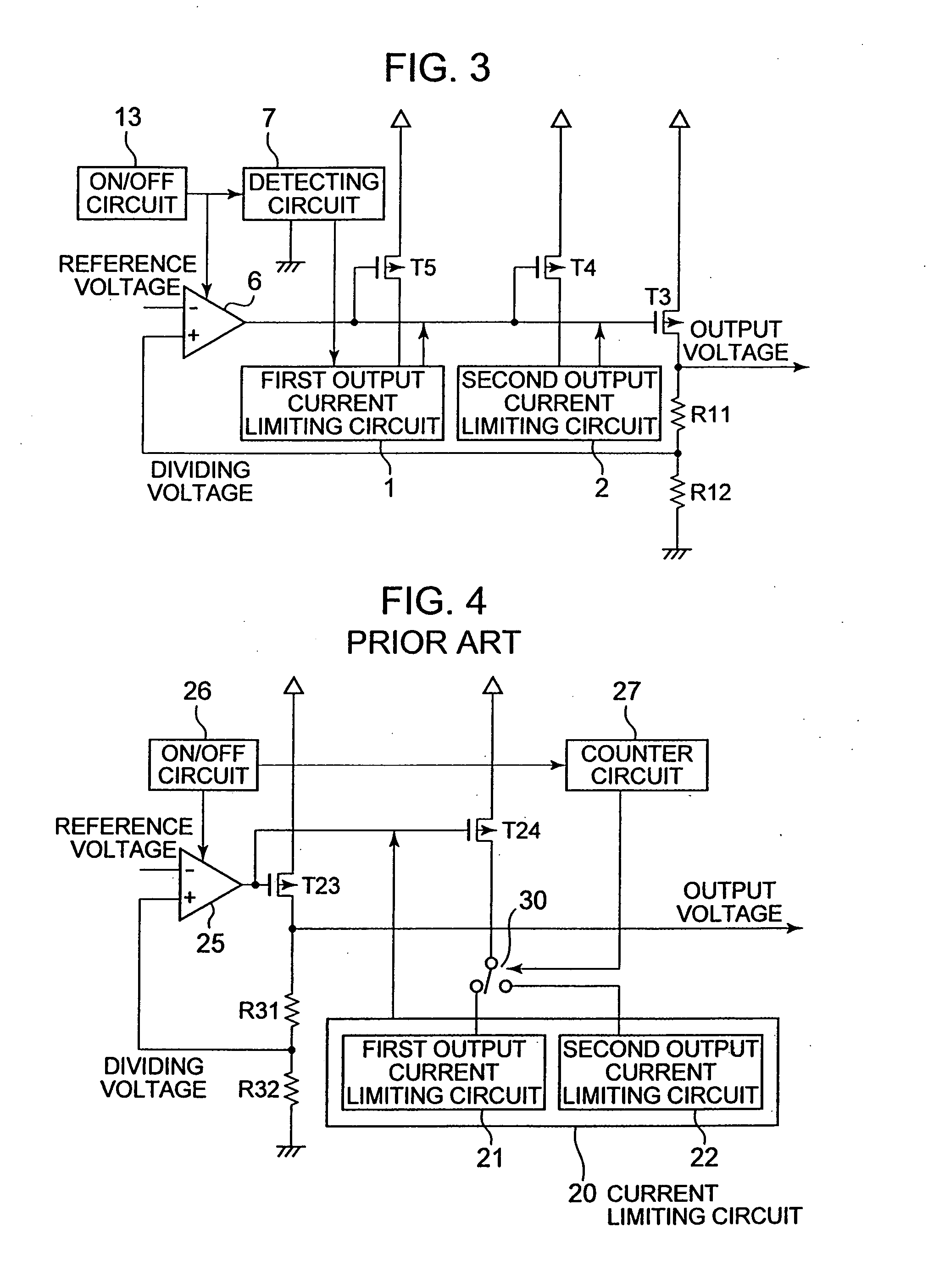
[0034]FIG. 3 is a block diagram showing a voltage regulator according to Embodiment 2. The voltage regulator according to Embodiment 2 has a structure in which an on / off circuit 13 is further provided in the voltage regulator according to Embodiment 1.

[0035] The on / off circuit 13 performs the on / off control of the voltage regulator. The on / off circuit 13 has an output terminal connected with the amplifying circuit 6 and the detecting circuit 7. The on / off circuit 13 outputs a control signal to each of the amplifying circuit 6 and the detecting circuit 7 in response to a signal from an outside to perform the on / off control of the voltage regulator.

[0036] The voltage regulator according to Embodiment 2 operates as follows.

[0037] When the voltage regulator is turned on, the on / off circuit 13 outputs the control signal to each of the amplifying circuit 6 and the detecting circuit 7 to turn on the voltage regulator. Then, the detecting circuit 7 detects the rise speed of the input vol...


PUM


Abstract

Provided is a voltage regulator in which a rush current of an output circuit can be limited and a rise time of an output voltage is short. The voltage regulator includes a first output current limiting circuit and a second output current limiting circuit which are used to control the output circuit, and a detecting circuit for detecting a rise speed of an input voltage. The operation of the first output current limiting circuit whose detection current value is low is controlled by the detecting circuit.

Description

[0001] This application claims priority under 35 U.S.C. § 119 to Japanese Patent Application No. JP2006-195462 filed Jul. 18, 2006, the entire content of which is hereby incorporated by reference. BACKGROUND OF THE INVENTION [0002] 1. Field of the Invention [0003] The present invention relates to a voltage regulator for generating a constant voltage based on an input voltage. [0004] 2. Description of the Related Arts [0005] A mobile electronic device such as a mobile telephone is generally operated by power supplied from a rechargeable battery. An output voltage of the rechargeable battery changes corresponding to a charging state. In order to stably operate the mobile electric device, it is necessary to apply a constant voltage to the mobile electric device. Therefore, the mobile electric device includes a voltage regulator for generating a constant voltage without depending on the output voltage of the rechargeable battery. For circuit protection, the voltage regulator includes a ...

Claims


Application Information

Patent Timeline
Patent Type & Authority Applications(United States)
IPC IPC(8): G05F1/565
CPCY10S323/908G05F1/56
Inventor SUZUKI, TERUO
Owner ABLIC INC
Why Eureka
Try Eureka