Power supply circuit

a power supply circuit and circuit technology, applied in the direction of power conversion systems, dc-dc conversion, instruments, etc., can solve the problems of increased output signal error in response, delayed internal operation of digital control circuits, ripples, etc., and achieve the effect of reducing the rising time of an output voltage from the power supply circui

Inactive Publication Date: 2017-10-05
SEMICON ENERGY LAB CO LTD
View PDF0 Cites 0 Cited by
  • Summary
  • Abstract
  • Description
  • Claims
  • Application Information

AI Technical Summary

Benefits of technology

[0005]The ripple caused at the output voltage of the power supply circuit will result in longer rising time for the output voltage of the power supply circuit.
[0007]In addition, an object of one embodiment of the disclosed invention is to suppress generation of ripple at the output voltage of a power supply circuit, thereby reducing the rising time of an output voltage from the power supply circuit.
[0016]In addition, according to one embodiment of the disclosed invention, the rising time of an output voltage from the power supply circuit can be reduced.

Problems solved by technology

However, in a digital control circuit, internal operation of the digital control circuit is delayed because the digital control circuit is operated with clock signals and discontinuous data is controlled.
Therefore, in the digital control circuit, the error in output signal will be increased in response to rapid changes in input signal.
This increased error produces the problem of ripple caused at the output voltage of the power supply circuit.
The ripple caused at the output voltage of the power supply circuit will result in longer rising time for the output voltage of the power supply circuit.

Method used


Image

  • Power supply circuit
  • Power supply circuit
  • Power supply circuit

Examples


Embodiment Construction

[0020]Embodiments of the invention disclosed will be described below with reference to the drawings. It is to be noted that the invention is not limited to the following description, and those skilled in the art can easily understand that modes and details of the invention can be changed in various ways without departing from the spirit and the scope of the invention. Therefore, it should be noted that the present invention is not to be considered interpreted as being limited to the following description of the embodiments.

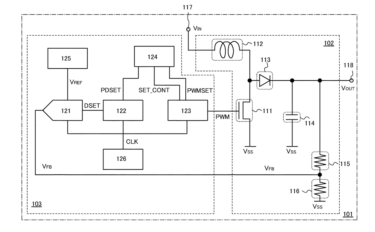
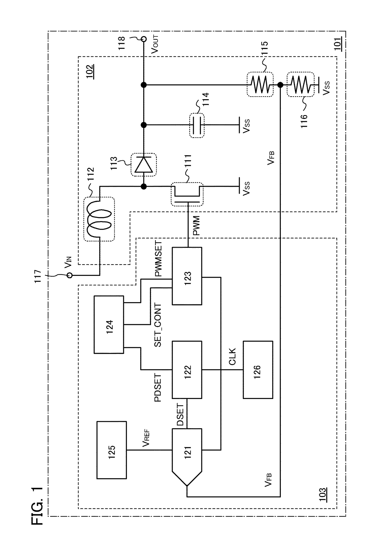
[0021]FIG. 1 shows an example of the configuration of a power supply circuit 101.

[0022]The power supply circuit 101 includes a voltage converter circuit 102, a digital control circuit 103 for controlling the voltage converter circuit 102, a terminal 117 to which a power supply voltage VIN is input, and a terminal 118 to which an output voltage VOUT is output. The voltage converter circuit 102 according to the present embodiment is a DC-DC converter including a tra...


PUM


Abstract

A power supply circuit includes: an analog / digital converter for converting an analog signal to a digital signal; a pulse width modulation signal control circuit for generating a setting control signal varying in accordance with the difference between a reference voltage and a feedback voltage and a control signal for controlling a pulse width modulation signal, which is based on the digital signal; and a pulse width modulation signal generation circuit for generating the pulse width modulation signal, to which the count signal and the control signal are input, in which the control signal controls the duty cycle of the pulse width modulation signal, and the setting control signal controls the cycle of updating the duty cycle of the pulse width modulation signal.

Description

BACKGROUND OF THE INVENTION1. Field of the Invention[0001]One embodiment of the disclosed invention relates to a power supply circuit.2. Description of the Related Art[0002]Conventionally, power supply circuits such as a switching regulator have been used for a wide range of electronic appliances typified by an image capturing device and a display device. Portable information terminals such as a cellular phone or a game machine have a power supply circuit incorporated therein.[0003]This type of power supply circuit includes a digital control circuit or an analog control circuit for controlling a voltage converter circuit. The digital control circuit for use in the power supply circuit can have fewer components than the analog control circuit, thereby allowing reduction in size (see Patent Document 1).REFERENCE[Patent Document 1] Japanese Published Patent Application No. 10-14234SUMMARY OF THE INVENTION[0004]However, in a digital control circuit, internal operation of the digital con...

Claims


Application Information

Patent Timeline
Patent Type & Authority Applications(United States)
IPC IPC(8): H02M3/157
CPCH02M2001/0025H02M3/157H02M1/0025H02M1/14H02M3/28
Inventor OHMARU, TAKURO
Owner SEMICON ENERGY LAB CO LTD
Why Eureka
Try Eureka