Conveyor apparatus

a technology of conveying apparatus and conveyor, which is applied in the direction of conveying, transportation and packaging, escalators, etc., can solve the problems of difficult inverting steps, speed irregularities that can easily occur, and insufficient driving force cannot be transmitted by only the driving mechanism disposed on the chain end, so as to achieve convenient ride quality and prevent local abrasion of the circulating chain

Inactive Publication Date: 2008-03-06
TOSHIBA ELEVATOR KK
View PDF6 Cites 18 Cited by
  • Summary
  • Abstract
  • Description
  • Claims
  • Application Information

AI Technical Summary

Benefits of technology

[0049] According to the present invention, even when a general step chain is driven, the step chain can be appropriately driven while maintaining a deep meshing. Further, local abrasion of the circulating chains can be prevented to provide a comfortable ride quality on the steps.

Problems solved by technology

However, in a conveyor in which a travel distance of the steps are long, there is a possibility that a sufficient driving force cannot be transmitted by only the driving mechanism disposed on the chain end, because of an increased load applied to the step chain.
However, when such a tooth chain 102 of a long link length is used as a step chain, a speed irregularity may easily occur, as compared with a general step chain, at an end of the conveyor where the tooth chain 102 turns to change directions.
Thus, it is difficult to invert the steps 101 with the use of a circular sprocket which is uniformly rotated.
As a result, a driving mechanism using an inexpensive and general sprocket is difficult to be used as a driving mechanism for driving a step chain.
However, a general step chain is of a short link length, so that a sufficient meshing angle cannot be guaranteed to drive circulating chain in circulation.
However, in a driving mechanism disposed at an intermediate position of a conveyor apparatus, when circulating chain whose link length is equal to or larger than that of a conveyor chain is driven in circulation by a general sprocket, the number of teeth of the sprocket is not enough.
Thus, pulsing motions occur in the circulating chains and the step chain to thereby impair a ride quality of a step.

Method used


Image

  • Conveyor apparatus
  • Conveyor apparatus
  • Conveyor apparatus

Examples


first embodiment

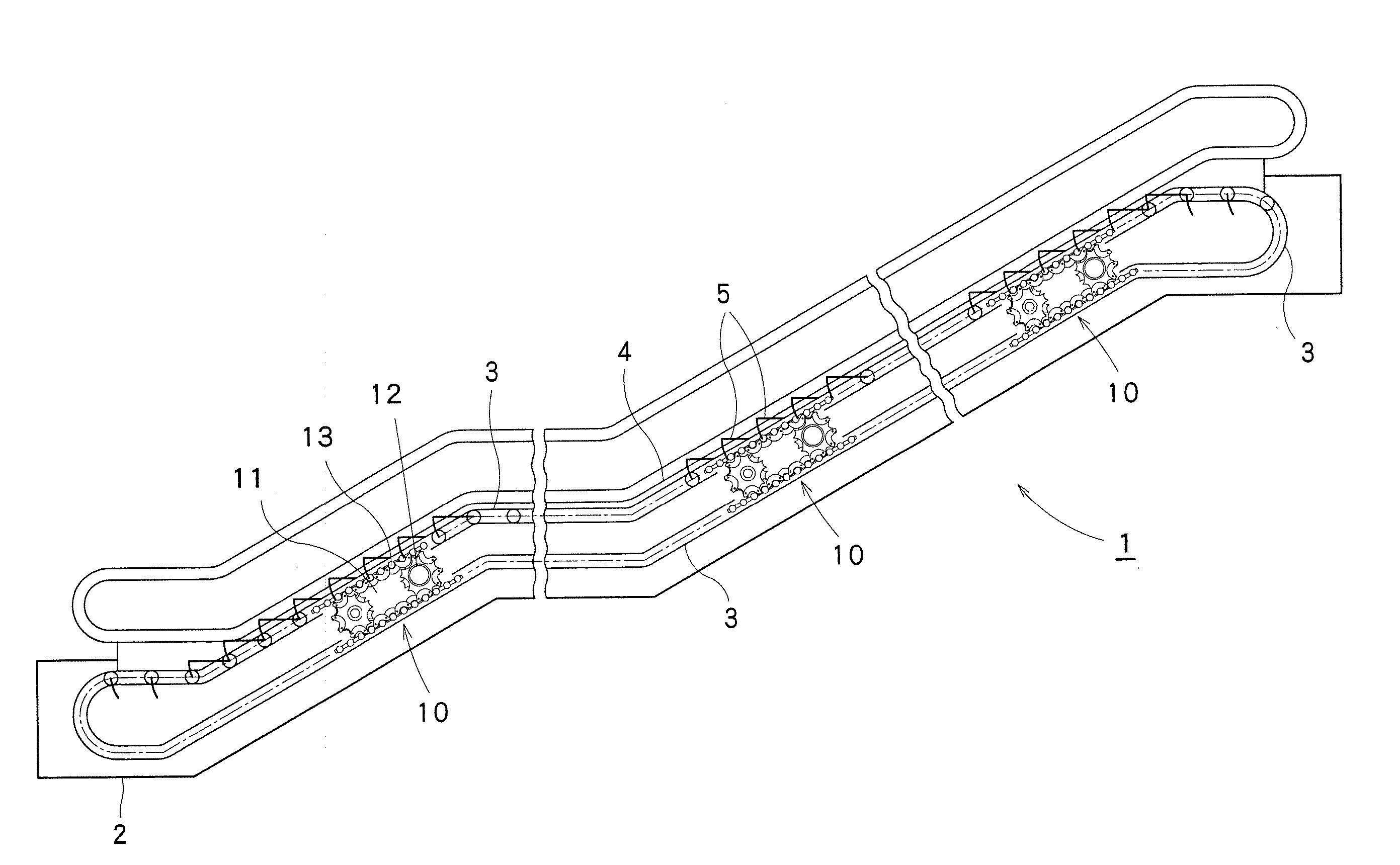
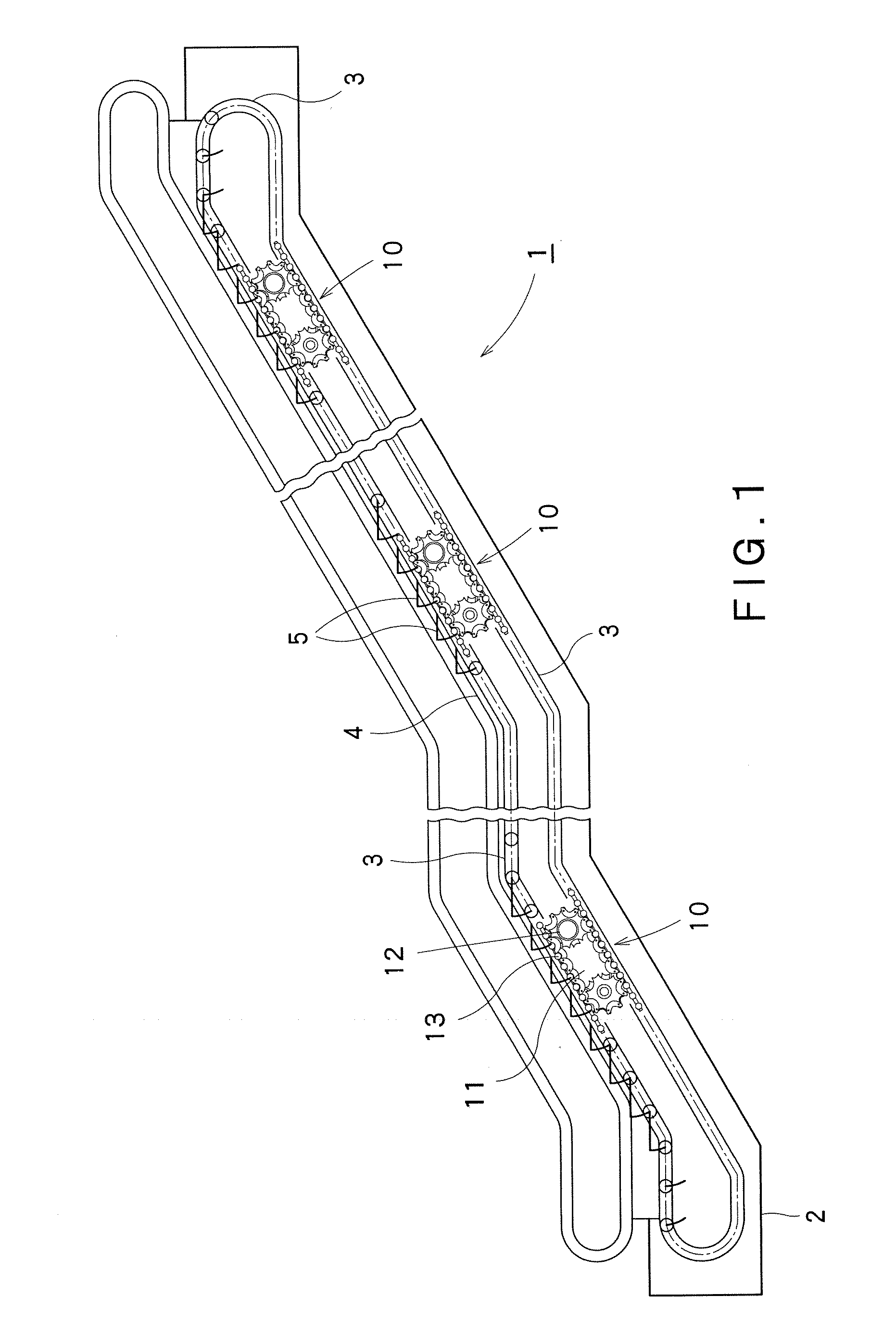
[0066] A first embodiment of the present invention is described below with reference to FIGS. 1 to 10.

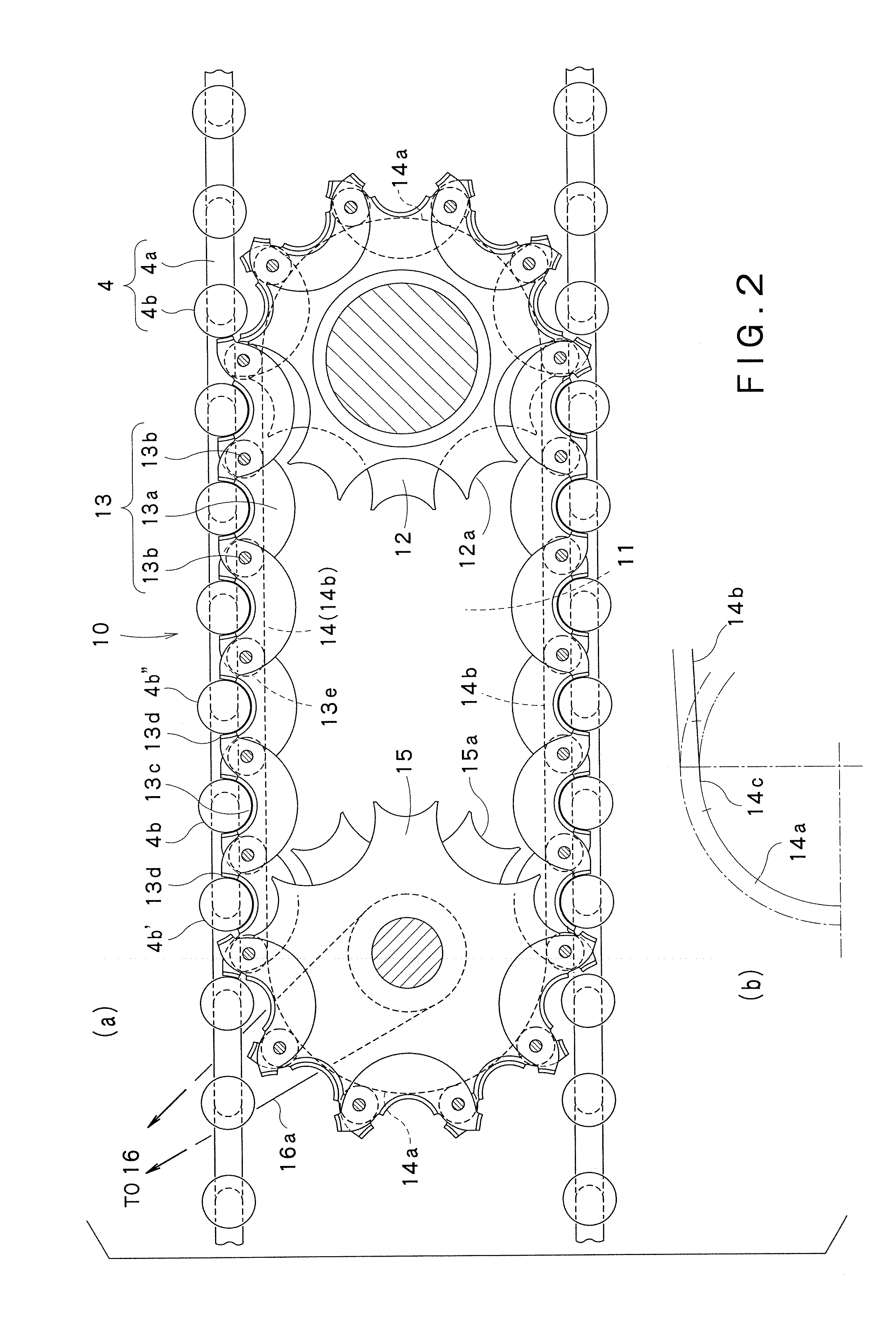
[0067]FIG. 1 is a side view of a conveyor apparatus in a first embodiment of the present invention. FIGS. 2(a) and 2(b) are side views of a chain driving mechanism of the conveyor apparatus in the first embodiment of the present invention. FIG. 3 is a plan view of the chain driving mechanism of the conveyor apparatus in the first embodiment of the present invention. FIG. 4 is a front sectional view of the chain driving mechanism of the conveyor apparatus in the first embodiment of the present invention. FIG. 5 is front sectional view of a circulating chain of the chain driving mechanism of the conveyor apparatus in the first embodiment of the present invention. FIG. 6 is a perspective view of a part of the circulating chain of the chain driving mechanism of the conveyor apparatus in the first embodiment of the present invention. FIG. 7 is a view illustrating a shape and an operatio...

second embodiment

[0110] Next, a second embodiment of the present invention is described with reference to FIGS. 11 and 12. FIG. 11 is a side view of a chain driving mechanism of a conveyor apparatus in a second embodiment of the present invention. FIG. 12 is an enlarged view of a part of a rail for circulation.

[0111] The second embodiment shown in FIGS. 11 and 12 differs from the first embodiment in that a step chain 21 is provided with a sectoral part 21′ of a larger curvature radius, but other structures and effects are substantially the same as those of the first embodiment. In FIGS. 11 and 12, the same parts as those in the first embodiment shown in FIGS. 1 to 10 are depicted by the same reference numbers, and the detailed description thereof is omitted.

[0112] At first, a schematic structure of the conveyor apparatus in this embodiment is described with reference to FIG. 11.

[0113] As shown in FIG. 11, the step chain 21 includes a step links 21a and step rollers 21b. Each of circulating chains...

third embodiment

[0125] Next, a third embodiment of the present invention is described with reference to FIGS. 13 to 15.

[0126]FIG. 13 is a schematic view of a tensioner mechanism disposed on a chain driving mechanism of a conveyor apparatus in a third embodiment of the present invention. FIG. 14 is a side view of a driving sprocket (driven sprocket) of the chain driving mechanism. FIG. 15 is a front sectional view of a part near circulating chain of the chain driving mechanism. In the third embodiment, as shown in FIG. 13, there is additionally disposed a tensioner mechanism 31 for moving a driven sprocket 15 of a chain driving mechanism 10 in a direction close to and apart from a driving sprocket 12, so as to adjust a tensile force of the circulating chain 13. In the third embodiment, as shown in FIG. 14, a margin gap dp for promoting disengagement of a chain link 13a is disposed in each of the tooth spaces formed in plate teeth 12a (15a) of the driving sprocket 12 (and the driven sprocket 15) to ...


PUM


Abstract

There is provided a conveyor apparatus free of pulsing motion in circulating chains to provide a comfortable ride quality on steps.
A conveyor apparatus 1 includes a step guide rail 3, a plurality of steps 5, a step chain 4, and a chain driving mechanism 10 for driving the step chain 4. The chain driving mechanism 10 includes a rotating and driving unit 11, a driving sprocket 12 which is rotated by a driving force given by the rotating and driving unit 11, and circulating chain 13 for giving a thrust to the step chain 4. The circulating chain 13 has chain links 13a and hinges 13b to be connected to the adjacent chain links 13a. The chain link 13a includes a placing surface 13c on which the step roller 4b is placed, and pressing surfaces 13d and 13d that are in contact with step rollers 4b.

Description

CROSS REFERENCE TO PRIOR APPLICATION [0001] This application claims priority from Japanese Patent Application No. 2006-235636 filed on Aug. 31, 2006, and Japanese Patent Application No. 2007-182051 filed on Jul. 11, 2007. The entire contents of this application are incorporated herein by reference. FIELD OF THE INVENTION [0002] The present invention relates to a conveyor such an escalator and a moving walkway. More particularly, it pertains to a conveyor apparatus free of pulsing motion in circulating chains to provide a comfortable ride quality on steps. BACKGROUND ART [0003] A conveyor such as an escalator and a moving platform includes a plurality of steps each having guide rollers on front and rear sides. These steps are supported by the guide rollers that are engaged with step guide rails provided in a structure, and the steps are circulated between an entrance port and an exit port, while horizontal postures of the steps are maintained. The steps are generally connected to eac...

Claims


Application Information

Patent Timeline
Patent Type & Authority Applications(United States)
IPC IPC(8): B66B21/02B66B21/00B66B23/06
CPCB66B23/028B66B23/02
Inventor ISHIKAWA, YOSHINOBUTONOKI, KENZOKOYAMA, TAIHEIOGIMURA, YOSHIOKIKUCHI, TAKAYUKIOKU, NOBUHIROMURAKAMI, SHINKAWAMOTO, HITOSHI
Owner TOSHIBA ELEVATOR KK
Why Eureka
Try Eureka