Electrically powered suspension system

a suspension system and electric technology, applied in the direction of resilient suspensions, vehicle springs, vehicle components, etc., can solve the problems of reducing the estimation accuracy of vehicle state amounts, affecting the quality of ride, and affecting the accuracy of damping control of actuators, etc., to achieve a comfortable level of ride quality

Pending Publication Date: 2022-06-16
HONDA MOTOR CO LTD
View PDF8 Cites 0 Cited by
  • Summary
  • Abstract
  • Description
  • Claims
  • Application Information

AI Technical Summary

Benefits of technology

[0013]The present invention has been made in view of the above-described circumstances and it is an object of the invention to provide an electrically powered suspension system that can keep the ride quality at a comfortable level even when a vehicle is traveling on a wavy road which causes pitching actions of the vehicle.
[0015]With the electrically powered suspension system of the embodiment can keep the ride quality at a comfortable level even when a vehicle is traveling on a wavy road which causes pitching actions of the vehicle.

Problems solved by technology

However, the electrically powered suspension system disclosed in Patent Literature 1 could possibly suffer from a decrease in the estimation accuracy of the vehicle state amounts (stroke speeds, sprung speed) in a case where the vehicle is traveling on a wavy road which causes pitching actions of the vehicle.
This makes it difficult to perform damping control of the actuators with high accuracy.
Consequently, the ride quality of the vehicle could be deteriorated.

Method used


Image

  • Electrically powered suspension system
  • Electrically powered suspension system
  • Electrically powered suspension system

Examples


Embodiment Construction

[0024]An electrically powered suspension system 11 according to an embodiment of the present invention will be described in detail below with reference to the drawings as appropriate.

[0025]Note that, in the drawings discussed hereinafter, basically, members having the same function are denoted by the same reference sign. In this case, as a general rule, a redundant description will be omitted. For convenience of explanation, sizes and shapes of components maybe schematically illustrated with deformation or in an exaggerated manner.

Basic Configuration Common to Electrically Powered Suspension Systems 11 According to Embodiments of the Present Invention

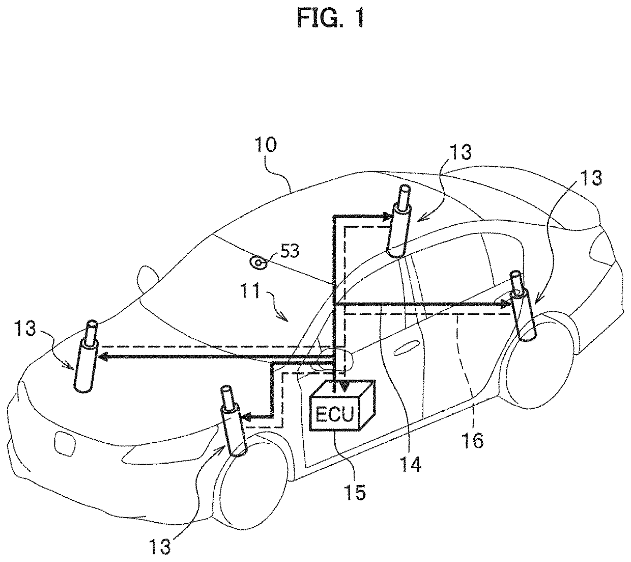
[0026]Firstly, a description will be given of a basic configuration common to the electrically powered suspension systems 11 according to the embodiments of the present invention with reference to FIGS. 1 and 2.

[0027]FIG. 1 is a view illustrating an entire configuration common to the electrically powered suspension systems 11 according ...


PUM


Abstract

An electrically powered suspension system includes: an electromagnetic actuator provided between a vehicle body and a wheel of a vehicle and configured to generate a damping force for damping vibration of the vehicle body; a wheel speed sensor that detects a wheel speed of the wheel; a wheel speed variation amount calculation part that calculates a wheel speed variation amount on the basis of wheel speed detection values detected by the wheel speed sensor; a 3D gyro sensor that detects sprung state amounts including a sprung pitching action of the vehicle; and a wheel speed variation amount correction part that estimates a variation component in the wheel speed variation amount on the basis of a sprung pitch amount and corrects the wheel speed variation amount so as to reduce the estimated variation component.

Description

CROSS-REFERENCE TO RELATED APPLICATIONS[0001]The present application claims the foreign priority benefit under Title 35 U.S.C. § 119 of Japanese Patent Application No. 2020-206178, filed on Dec. 11, 2020, in the Japan Patent Office, the disclosure of which is herein incorporated by reference in its entirety.BACKGROUND OF THE INVENTION1. Field of the Invention[0002]The present invention relates to an electrically powered suspension system including an actuator that is provided between a vehicle body and a wheel of a vehicle and generates a damping force for damping vibration of the vehicle body.2. Description of Related Art[0003]The applicant of the present disclosure has disclosed an electrically powered suspension system with an actuator that is provided between a (sprung) vehicle body and a (unsprung) wheel of a vehicle and generates a damping force for damping vibration of the vehicle body (see Japanese Patent Publication No. 2016-22830, hereinafter referred to as Patent Literatu...

Claims


Application Information

Patent Timeline
Patent Type & Authority Applications(United States)
IPC IPC(8): B60G17/015B60G17/06B60G17/0165
CPCB60G17/0157B60G17/06B60G17/0165B60G2400/208B60G2400/0512B60G2800/916B60G2202/44B60G2204/62B60G2500/104B60G2600/182B60G2800/162B60G2400/202B60G17/018B60G17/015B60G17/01933B60G17/01908B60G2401/28B60G2400/10B60G2400/106B60G2400/0523B60G2400/0522B60G2400/0521
Inventor KANDA, RYOMA
Owner HONDA MOTOR CO LTD
Why Eureka
Try Eureka