Circuit for detecting optical failures in a passive optical network

Inactive Publication Date: 2008-03-06
AVAGO TECH INT SALES PTE LTD
View PDF6 Cites 35 Cited by
  • Summary
  • Abstract
  • Description
  • Claims
  • Application Information

AI Technical Summary

Benefits of technology

[0010]The disclosed invention provides a circuit that allows fast and reliable detection of failures in passive optical networks (PONs). In accordance with one embodiment, the present invention detects rogue optical network unit (ONU) failu

Problems solved by technology

If these rules of operation are violated, the integrity of the system transmission can be severely compromised.
The disadvantage of the detection of rogue ONU based on the AP is the substantial delay in generating an indication on such failures.
This delay results from the time required for measuring the AP value, which is typically done using a low pass fi

Method used


Image

  • Circuit for detecting optical failures in a passive optical network
  • Circuit for detecting optical failures in a passive optical network
  • Circuit for detecting optical failures in a passive optical network

Examples


Example

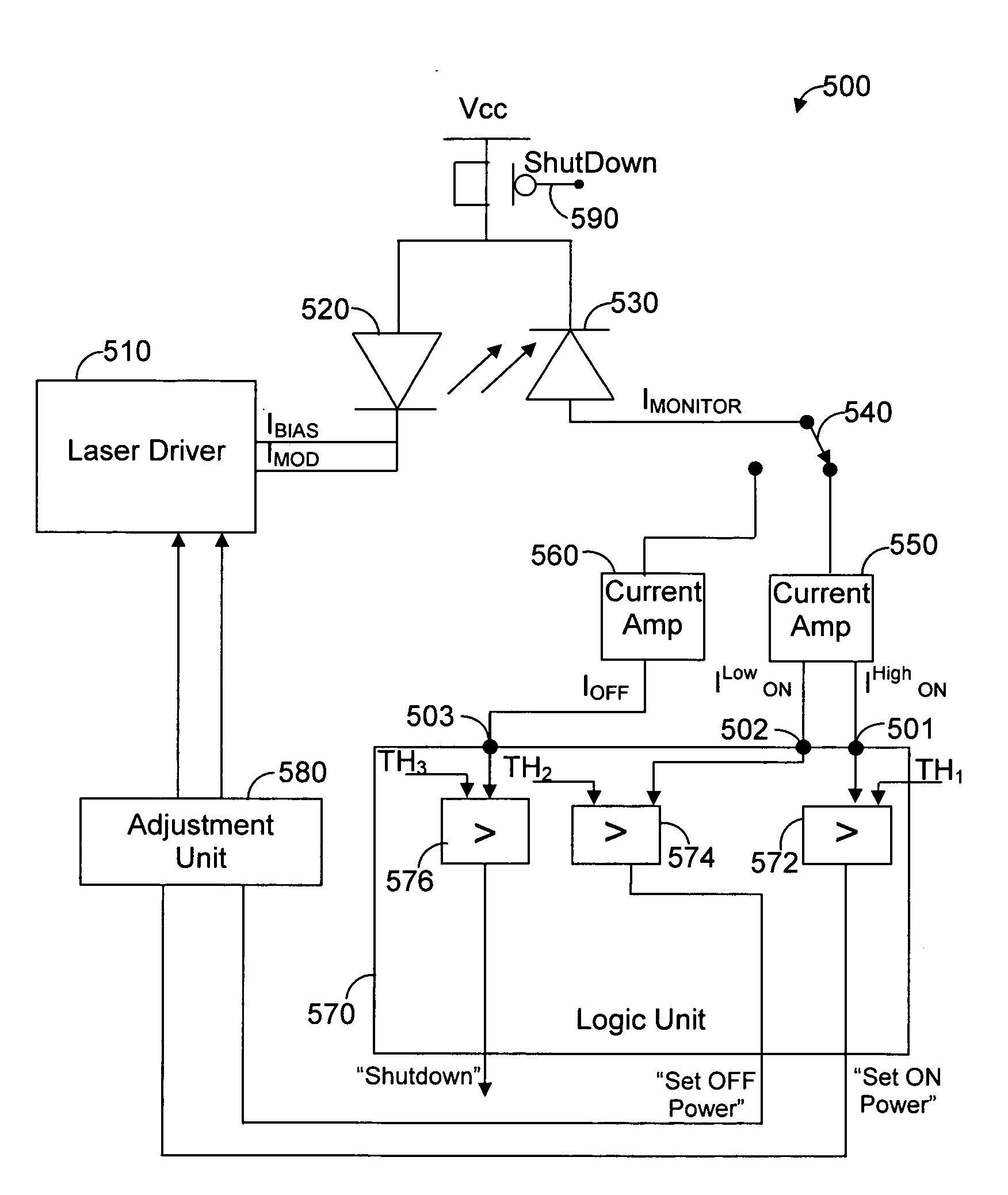
[0028]FIG. 3 shows an exemplary and non-limiting circuit 300 for measuring the output optical power level of a laser diode in accordance with the principles of the present invention. The circuit 300 includes a laser diode driver 310, a laser diode 320, a photodiode 330, a switch 340, and current amplifiers 350 and 360. The laser diode driver 310 is coupled to the laser diode 320 and produces a bias current IBIAS and a modulation current IMOD. The bias current IBIAS is a continuous fixed current that is usually necessary to ensure proper dynamic performance of the laser diode 320. The modulation current IMOD is superimposed on the bias current IBIAS during ON times for producing an optical signal that varies as a function of the modulation current IMOD. The laser diode 320 produces optical signals based on the IBIAS and IMOD provided by the laser diode driver 210. Specifically, The IBIAS and IMOD current signals respectively determine the power level of the output signal during OFF a...


PUM


Abstract

A circuit for detecting optical failures in a passive optical network (PON) wherein digital burst data transmitted by an optical transmitter is monitored by a photodiode, includes a power determination unit coupled to the photodiode for providing measurements of an output optical power of a high logic level and a low logic level of the digital burst data during ON times of the optical transmitter and for providing a measurement of an output optical power during OFF times of the optical transmitter. A logic unit coupled to the power determination unit is responsive to the measurements for generating control and calibration signals. Such a circuit may be used for detecting rogue optical network unit (ONU) failure or eye safety hazards in a passive optical network (PON) wherein digital burst data transmitted by an optical transmitter is monitored by a photodiode.

Description

REFERENCESPatents and Published Applications[0001]U.S. Pat. No. 6,650,839Nov 2003Mallard, Jr., et al.U.S. Pat. No. 6,115,163Sep 2000NobuharaU.S. Pat. No. 6,108,112Aug 2000ToumaU.S. Pat. No. 20020076143Jun 2002FoltzerFIELD OF THE INVENTION[0002]This invention relates generally to passive optical networks, and more particularly to techniques for detecting optical failures in such networks.BACKGROUND OF THE INVENTION[0003]A passive optical network (PON) is shared between multiple optical network units (ONUs), where each ONU must transmit data to the common channel only during assigned time slots. If these rules of operation are violated, the integrity of the system transmission can be severely compromised.[0004]An exemplary diagram of a typical PON 100 is schematically shown in FIG. 1. The PON 100 includes a number M of ONUs 120-1, 120-2, through 120-M, coupled to an optical line terminal (OLT) 130 via a passive optical splitter 140. Since all ONUs function in like manner, they will be...

Claims


Application Information

Patent Timeline
IPC IPC(8): H04B10/04
CPCH04B10/0793H04Q2011/0079H04Q11/0067H04B10/07955
Inventor WEBER, RAVIVKOREN, ASAF
Owner AVAGO TECH INT SALES PTE LTD
Why Eureka
Try Eureka