Electronic equipment and method for controlling electronic equipment

An electronic device and a technology for controlling electronics, which can be used in program control design, television, hardware monitoring, etc., and can solve problems such as difficult detection and failure to restore abnormal states

Inactive Publication Date: 2002-12-11
SONY CORP
View PDF4 Cites 0 Cited by
  • Summary
  • Abstract
  • Description
  • Claims
  • Application Information

AI Technical Summary

Problems solved by technology

In this case, there is a problem that even if the parameter value is set to an outlier value when it is abnormal, the value is regarded as a normal value, and it is difficult to detect that the value is an outl...

Method used


Image

  • Electronic equipment and method for controlling electronic equipment
  • Electronic equipment and method for controlling electronic equipment
  • Electronic equipment and method for controlling electronic equipment

Examples


Embodiment Construction

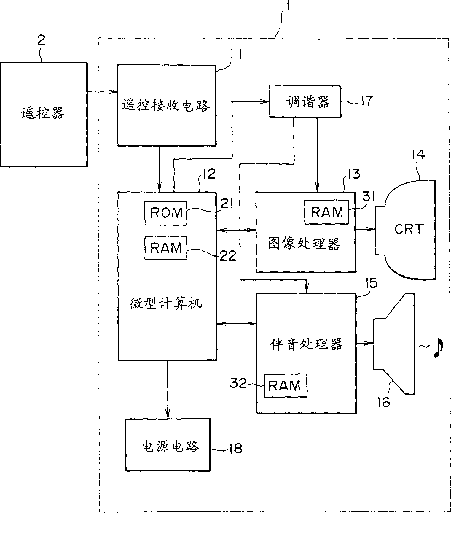
[0031] figure 1 One structural example of a television receiver employing the electronic equipment of the present invention is shown. In this embodiment, the television receiver 1 is remotely controlled by a far infrared signal of a remote controller 2 .

[0032] The television receiver 1 includes a remote control receiving circuit 11 for receiving an infrared signal output from the remote controller 2, and the remote control receiving circuit 11 outputs its detection signal to the microcomputer 12 when the infrared signal is received. According to a program stored in the ROM 21, the microcomputer 12 controls the corresponding parts, and stores necessary data, programs and the like in the RAM 22 correctly.

[0033] A tuner 17 demodulates a TV broadcast signal received via an unshown antenna, outputs its video signal to an image processor 13 and outputs its audio signal to an audio processor 15 . The image processor 13 processes the input video signal and outputs to the CRT ...


PUM


Abstract

The microcomputer outputs an instruction to the sound processor to set a volume value as a parameter, specifying that the volume output from the speaker is a predetermined value. The sound processor stores the value of the parameter in a RAM, and sets the volume corresponding to the stored value of the parameter. The microcomputer reads out the parameter value actually set by the sound processor, and determines whether the parameter value is different from the value that has been instructed to be set to it, and determines that an abnormality is generated in the sound processor when they are different from each other, and thus The occurrence of abnormality can be detected in a device that has no function of detecting the occurrence of abnormality.

Description

[0001] TECHNICAL FIELD The present invention relates to electronic equipment and a method of controlling the electronic equipment, and more particularly, to a monitor and a monitoring method capable of accurately detecting an abnormality of a circuit device inside a television receiver. Background technique [0002] Figure 5 A structural example of the audio section of a conventional television receiver is shown. The microcomputer 41 includes a RAM 51 for controlling a sound processor 43 in response to commands from an input section 42 . The sound processor 43 includes a built-in RAM 61, processes sound data and outputs the processed data to the speaker 44. [0003] The operation thereof will be described below. When the TV is powered on, the microcomputer 41 executes Figure 6 The processing shown in the flowchart in . First, start-up processing is performed in step S51. In the start-up process, the microcomputer 41 initializes the sound processo...

Claims


Application Information

Patent Timeline
IPC IPC(8): G06F11/30H04N7/18H04N17/04
CPCH04N17/04G06F11/22
Inventor 野原聪大冢庆子
Owner SONY CORP
Why Eureka
Try Eureka