Fall Arrest Lanyard

a technology of which is applied in the direction of safety belts, sports equipment, cleaning equipment, etc., can solve the problems that the prior art safety harness and lanyard system does not include additional accessories that provide, and achieve the effect of relieving or preventing the effects of suspension trauma

Active Publication Date: 2008-03-13
TECH SAFETY LINES
View PDF30 Cites 51 Cited by
  • Summary
  • Abstract
  • Description
  • Claims
  • Application Information

AI Technical Summary

Benefits of technology

This patent describes a device called a fall arrest lanthyard which helps stop people from falling but also makes them more comfortable during their descent. It has two parts: one part is designed to make the person's body relaxed by giving them something to hold onto, and another part can help shift the person's weight to someone who will save them.

Problems solved by technology

The technical problem addressed in this patent is the lack of effective measures to reduce or prevent suspension trauma injuries among workers who have fallen from heights and become temporarily suspended in their safety harnesses before being rescued. Existing safety harness and lanthyard systems offer no added features beyond basic materials strong enough to support the person's weight. This patent proposes an improvement through the development of an enhanced safety lanthyard system that offers both deceleration capabilities and an etrier system that can be activated automaticallly or manually by the worker themselves. It also suggests allowing the worker to perform a controlled weight transfer while still safely suspended until rescue occurs.

Method used


Image

  • Fall Arrest Lanyard
  • Fall Arrest Lanyard
  • Fall Arrest Lanyard

Examples


Embodiment Construction

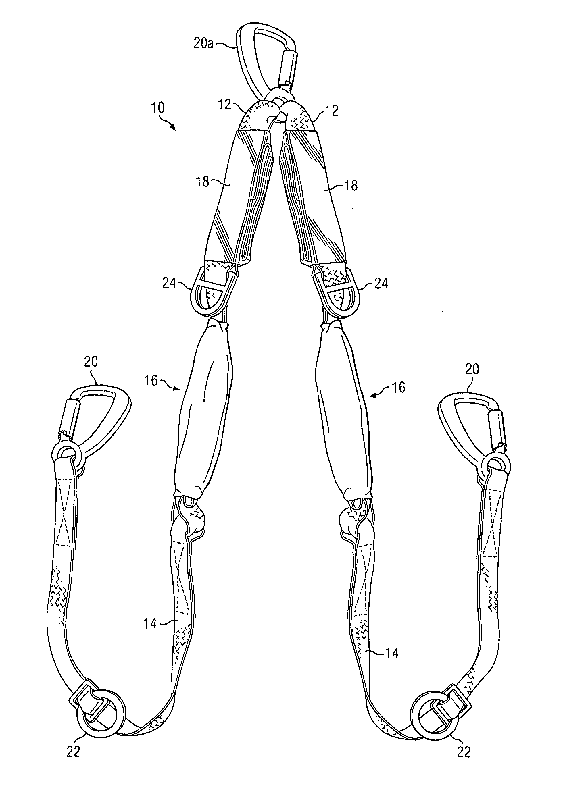
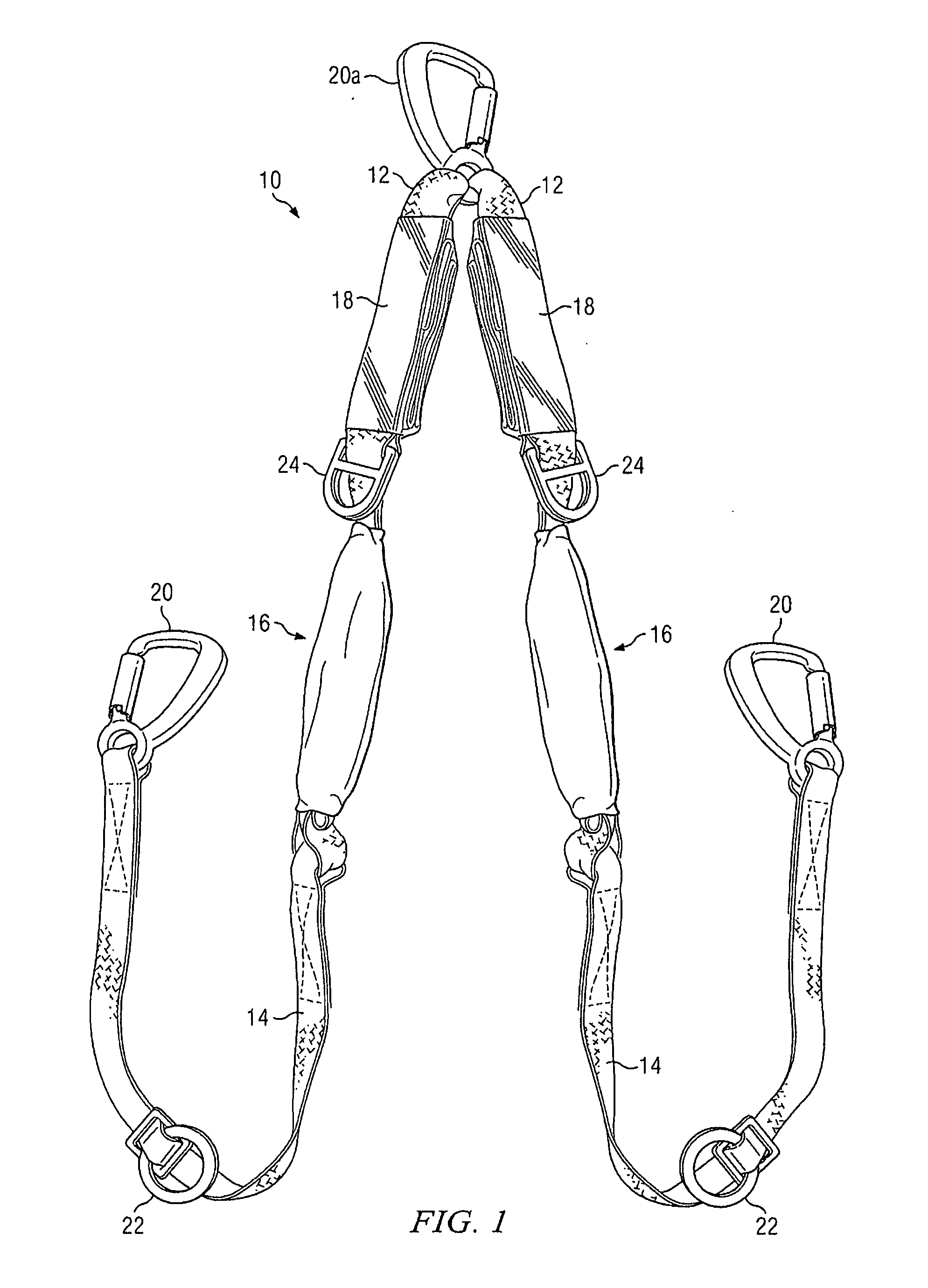
[0023]A preferred embodiment of the invention is disclosed herein as shown in FIGS. 1 through 3B. FIG. 1 shows the fall arrest lanyard 10 assembly in accordance with an embodiment of the present invention. In this embodiment, the lanyard assembly 10 is comprised of two upper straps 12 connected at one end via universal connectors of sufficient tensile strength, in this instance shown as clamp 20a, and two lower straps 14. Upper straps 12 and lower straps 14 are connected via sewn loops as shown in FIG. 1, although alternative connection devices may be utilized including universal clamps, lobster clamps and load bearing rings of requisite tensile strength. Upper straps 12 include a folded etrier 16 secured to each upper strap 12. Etrier packs 16 comprise a length of nylon strap with loops sewed therein that is folded and enclosed in a breakaway sheathing, such as shrink wrap. Etrier packs 16 are shown in the stored position wherein the etriers, a French term used by climbers to denot...


PUM


Abstract

An improved fall arrest lanyard apparatus and method for decelerating and arresting a user from impacting the ground after a fall, along with an integrated, deployable etrier. After the fall sequence has ended, the user may orient himself in a comfortable position using the deployed etrier so as to prevent or relieve the effects of suspension trauma while the user awaits rescue.

Description


Claims


Application Information

Patent Timeline
Owner TECH SAFETY LINES
Why Eureka
Try Eureka