Magnetic switch with auto-release function

a technology of magnetic switch and function, applied in the field of magnetic switch, can solve the problems of failure of lock, inconvenient unlocking procedure, obstructing the beauty of the outer appearance of the mobile electronic product,

Inactive Publication Date: 2008-03-13
JARLLYTEC CO LTD
View PDF10 Cites 76 Cited by
  • Summary
  • Abstract
  • Description
  • Claims
  • Application Information

AI Technical Summary

Problems solved by technology

Because each hook extends out of the cover and each hook hole is a recessed hole on one side of the base member, the arrangement of the at least one hook and the at least one hook hole obstructs the sense of beauty of the outer appearance of the mobile electronic product.
Further, the at least one hook may be deformed or broken accidentally, resulting in failure of the lock.
This unlocking procedure is inconvenient.

Method used


Image

  • Magnetic switch with auto-release function
  • Magnetic switch with auto-release function
  • Magnetic switch with auto-release function

Examples


Embodiment Construction

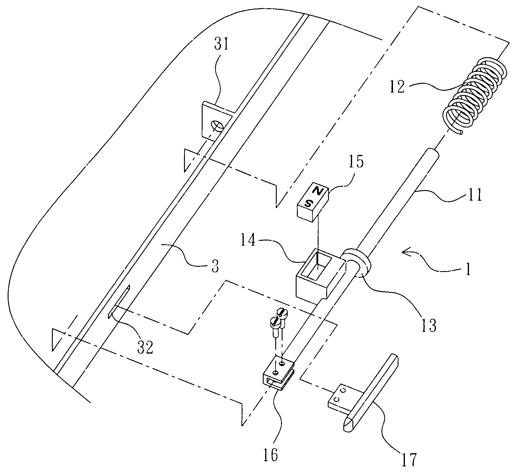
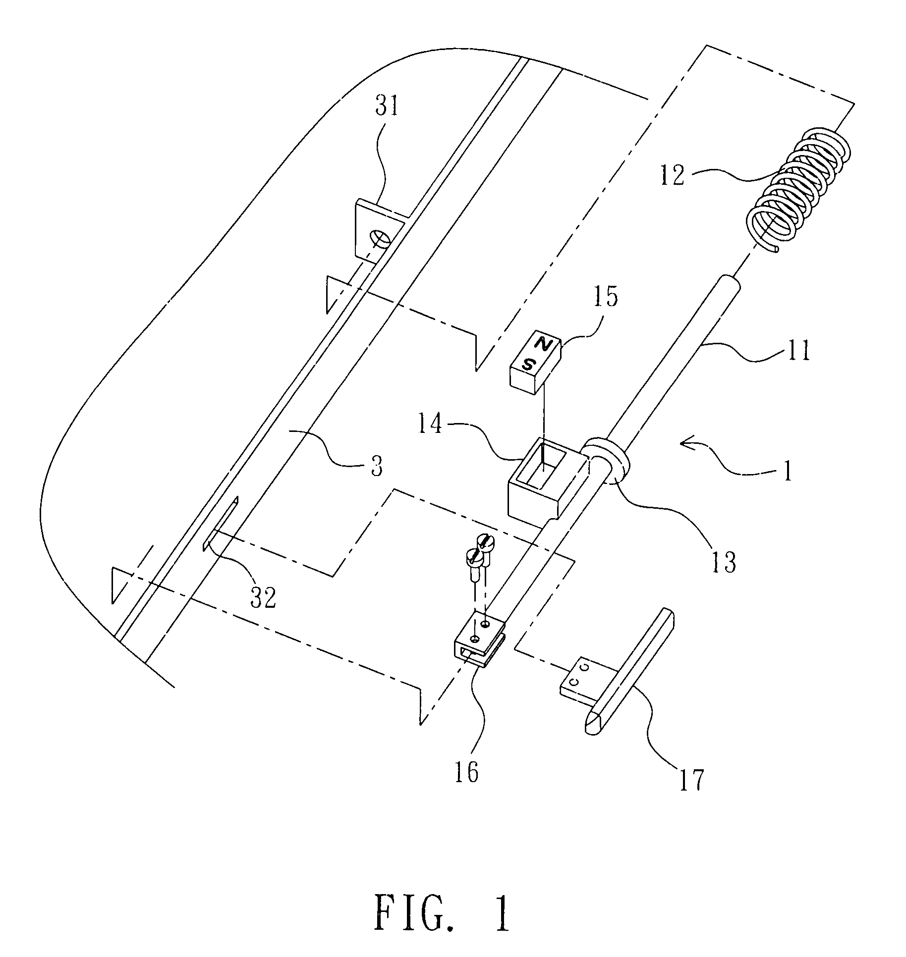
[0023]Referring to FIGS. 1 and 2, a magnetic switch in accordance with a first embodiment of the present invention is shown comprised of a movable unit 1 and a fixed unit 2.

[0024]The magnetic switch is used in a lifting cover type article, for example, an electronic product such as mobile computer, PDA, electronic dictionary, or the like. The movable unit 1 is mounted in the front end edge of the first member 3 of the two hinged members of the lifting cover type article, and the fixed unit 2 is mounted in the corresponding end edge the second member 4 of the two hinged members of the lifting cover type article. Alternatively, the movable unit 1 and the fixed unit 2 can be respectively mounted in the second member 4 and the first member 3.

[0025]The movable unit 1 comprises a driven rod 11, which is inserted with its one end through a lug 31 at the back side of the front end edge of the first member 3 and kept in parallel to the front end edge of the first member 3 and has a collar 13...


PUM


Abstract

A magnetic switch is disclosed to include a first magnetic device affixed to a second member of a lifting cover type of a article, a driven rod slidably mounted in a first member of the lifting cover type of the article that is hinged to the second member, a holder member mounted on the driven rod and holding a second magnetic device for attracting the first magnetic device to keep the fist member and the second member in the closed position, a spring member that imparts a pressure to the driven rod to hold the holder member in such a position that the second magnetic device attracts the first magnetic device, and a key extending out of the first member of the lifting cover type of the article for operation by hand to move the driven rod to the position where the second magnetic device repulses the first magnetic device to force the second member away from the first member.

Description

BACKGROUND OF THE INVENTION[0001]1. Field of the Invention[0002]The present invention relates generally to a magnetic switch and more particularly, to such a magnetic switch that provides an auto-release function.[0003]2. Description of the Related Art[0004]A mobile electronic product, for example, a notebook computer is comprised of a first member, i.e., the cover, a second member, i.e., the base member, a hinge structure coupled between the cover and the base member for allowing the cover to be opened from or closed on the base member, and a lock for locking the cover to the base member in the closed position. The lock comprises at least one hook movably mounted in the cover, and at least one key for operation by the user to move the at least one hook between a locking position where the at least one hook is respectively hooked in a respective hook hole in the base member and an unlocking position where the at least one hook is released from the respective hook hole. Because each ...

Claims


Application Information

Patent Timeline
Patent Type & Authority Applications(United States)
IPC IPC(8): E05C19/16
CPCE05C19/16Y10T292/11
Inventor LEE, YUNG-TACHEN, CHIA-CHENGKUO, HUNG-TA
Owner JARLLYTEC CO LTD
Why Eureka
Try Eureka