Composite resin window frame constructions for airplanes

a technology of composite resin and window frame, which is applied in the direction of transportation and packaging, efficient propulsion technologies, and other domestic objects, etc., can solve the problem that no other methods have existed

Inactive Publication Date: 2008-04-03
THE BOEING CO
View PDF12 Cites 57 Cited by
  • Summary
  • Abstract
  • Description
  • Claims
  • Application Information

AI Technical Summary

Problems solved by technology

Heretofore, no other methods have existed to eliminate the need for the...

Method used


Image

  • Composite resin window frame constructions for airplanes
  • Composite resin window frame constructions for airplanes
  • Composite resin window frame constructions for airplanes

Examples


example 2

[0051]Another composite resin window frame part of similar size and shape was fabricated using an intermediate modulus compression molding material, Toray BMS 8-276 carbon fiber epoxy prepreg tape material in accordance with the manufacturer's instructions. After molding, curing and cooling, another composite resin window frame of the present invention was thereby produced.

example 3

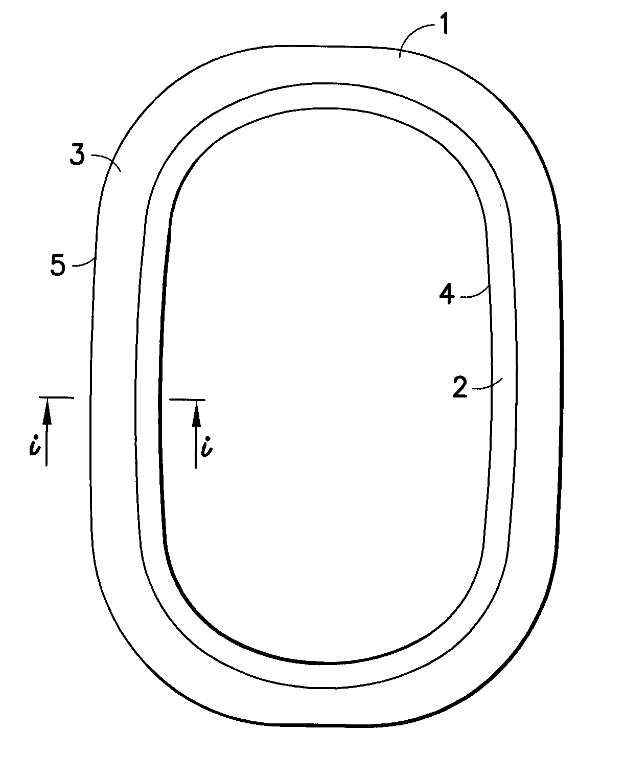
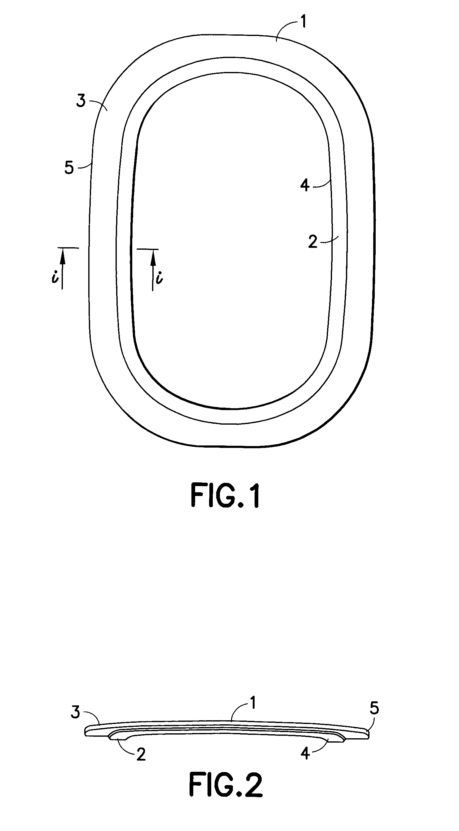
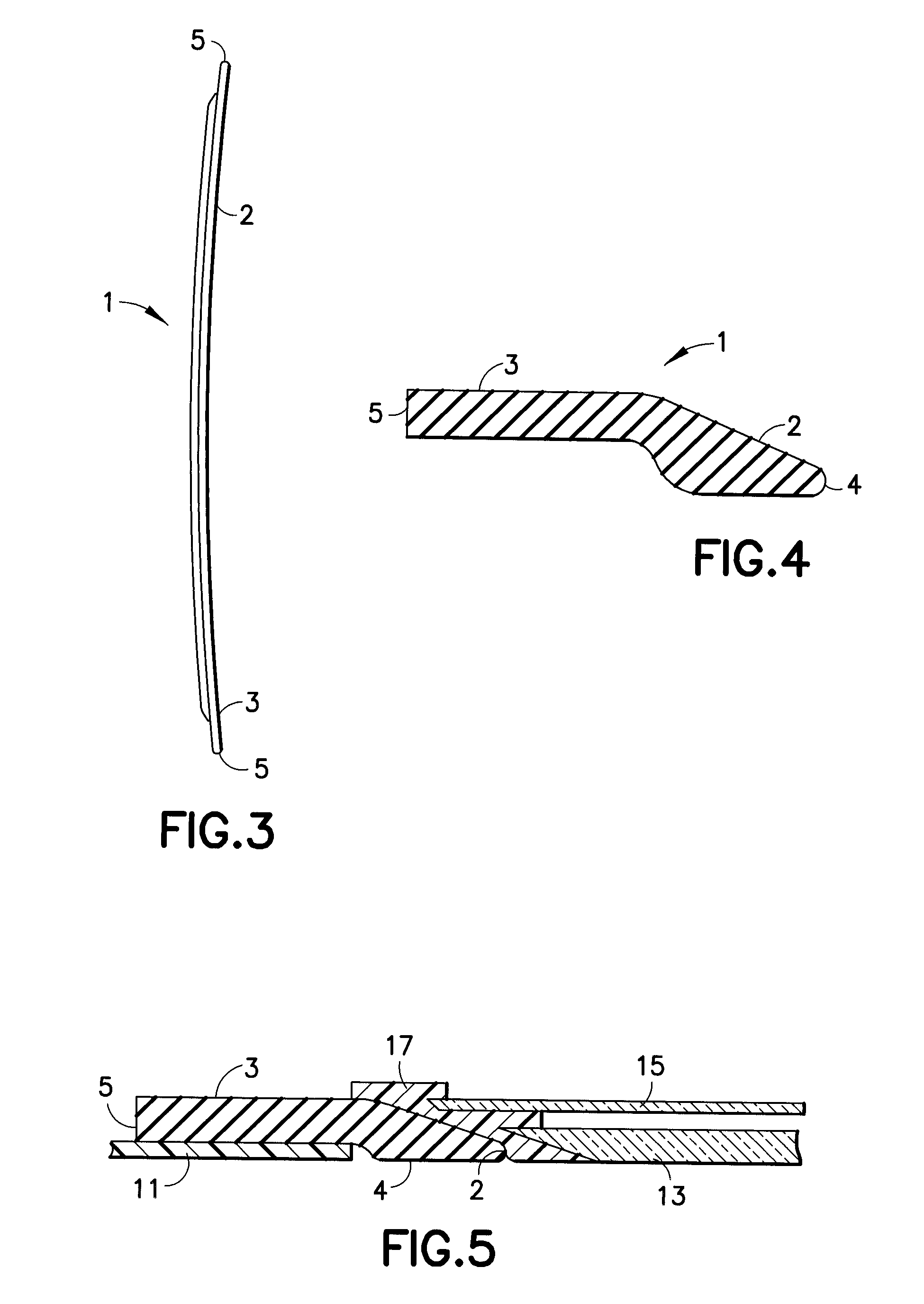
[0052]Composite resin window frames made in accordance with the foregoing examples were converted into window frame assemblies by combining each of the frames with acrylic transparencies by means of clips and a rubber seal and installing the combined assemblies in composite fuselage apertures of sufficient size to receive and complete an integrated frame-window-fuselage assembly. Stress and load analyses confirmed that the frames carried and transmitted the loads satisfactorily to the surrounding fuselage skin structure.


PUM

PropertyMeasurementUnit
Lengthaaaaaaaaaa
Lengthaaaaaaaaaa
Pressureaaaaaaaaaa

Abstract

A composite resin window frame for installation in a composite resin airplane fuselage has an inner flange for receiving and securely affixing an aircraft window transparency and an outer flange adapted for connection to the airplane fuselage structure. The frame has a generally flat configuration which does not require any additional strength enhancing member such as an additional flange perpendicular to the structure. The composite resin window frame has sufficient strength to securely affix a window transparency to a composite resin fuselage.

Description

BACKGROUND OF THE INVENTION [0001]1. Field of the Invention[0002]The present invention provides manufacturing improvements for airplanes utilizing composite resin window frame constructions.[0003]2. Prior Art[0004]Airplane window frame assemblies must be sufficiently strong to hold a window transparency in place while compensating for any loss of strength where the fuselage skin is pierced to receive the transparency. Airplane window frame assemblies are generally fabricated from metal constructions that offer strength but which traditionally suffer from weight concerns and corrosion deficiencies.[0005]Aluminum fuselages on current airplanes have forged window frames in combination with window belts having localized doublers around the windows. The upstanding flange used in prior art aluminum frames prevents skin buckling through and near the window cutout. The upstanding flange on such window frames is commonplace on aluminum airplanes and it also serves to guide installation of th...

Claims


Application Information

Patent Timeline
IPC IPC(8): B64C1/14
CPCB29C70/446B29C70/462Y02T50/433B64C1/1492B29L2031/005Y02T50/40E06B3/00
Inventor BAGGETTE, PHILLIP D.BRIGMAN, RICHARD W.DOPKER, BERNHARDJOHNSON, ROBERT W.SANDYS, JEFFERY P.
Owner THE BOEING CO
Why Eureka
Try Eureka