Honeycomb catalytic structure, precoated support for producing honeycomb catalytic structure, and process for producing honeycomb catalytic structure

Active Publication Date: 2008-05-29
NGK INSULATORS LTD
View PDF3 Cites 46 Cited by
  • Summary
  • Abstract
  • Description
  • Claims
  • Application Information

AI Technical Summary

Benefits of technology

[0031]In the first and second honeycomb catalytic structures of the present invention, the amount of catalyst layer supported is specified at an appropriate level; thereby, there can be appropriately suppressed the increase in pressure loss caused by the catalyst layer loaded on the inner surfaces of partition wall pores and the increase in the flow rate of the exhaust gas passing through pores and good catalytic activity can be obtained in the third and fourth honeycomb catalytic structures of the present invention, the 50% particle diameter (D50) and 90% particle diameter (D90) of the particles (catalyst particles) forming the catalyst layer are each specified at an appropriate level; thereby, the introduction of catalyst particles into pores of partition wall during the formation of catalyst layer can be made easy and the increase in pressure loss caused by the catalyst layer loaded on the inner surfaces of par

Problems solved by technology

That is, formation of catalyst layer on the inner surfaces of pores results in smaller pores, which invites a serious increase in pressure loss when the amount of catalyst layer loaded is too large.
When the flow rate of exhaust gas is too high, the efficiency of contact between catalyst layer and exhaust gas is lower and no sufficient purification ability is obtained.
Meanwhile, in a case where the amount of catalyst layer loaded is too small or introduction of catalyst particles which constitute the catalyst layer into pores is insufficient during the formation of catalyst layer and the catalyst layer is loaded only on the very small area of the inner surfaces of partition wall pores, the exhaust gas is unable to contact sufficiently with the catalyst layer during its passing through pores and no sufficient purification ability is obtained.
However, for example, when the particle diameters of catalyst particles are too large as compared with the diameters of pores, introduction of catalyst particles into pores

Method used


Image

  • Honeycomb catalytic structure, precoated support for producing honeycomb catalytic structure, and process for producing honeycomb catalytic structure
  • Honeycomb catalytic structure, precoated support for producing honeycomb catalytic structure, and process for producing honeycomb catalytic structure
  • Honeycomb catalytic structure, precoated support for producing honeycomb catalytic structure, and process for producing honeycomb catalytic structure

Examples


examples

[0108]The present invention is described in more detail below by way of Examples. However, the present invention is in no way restricted to these Examples.

examples 1 to 22

, Comparative Examples 1-3

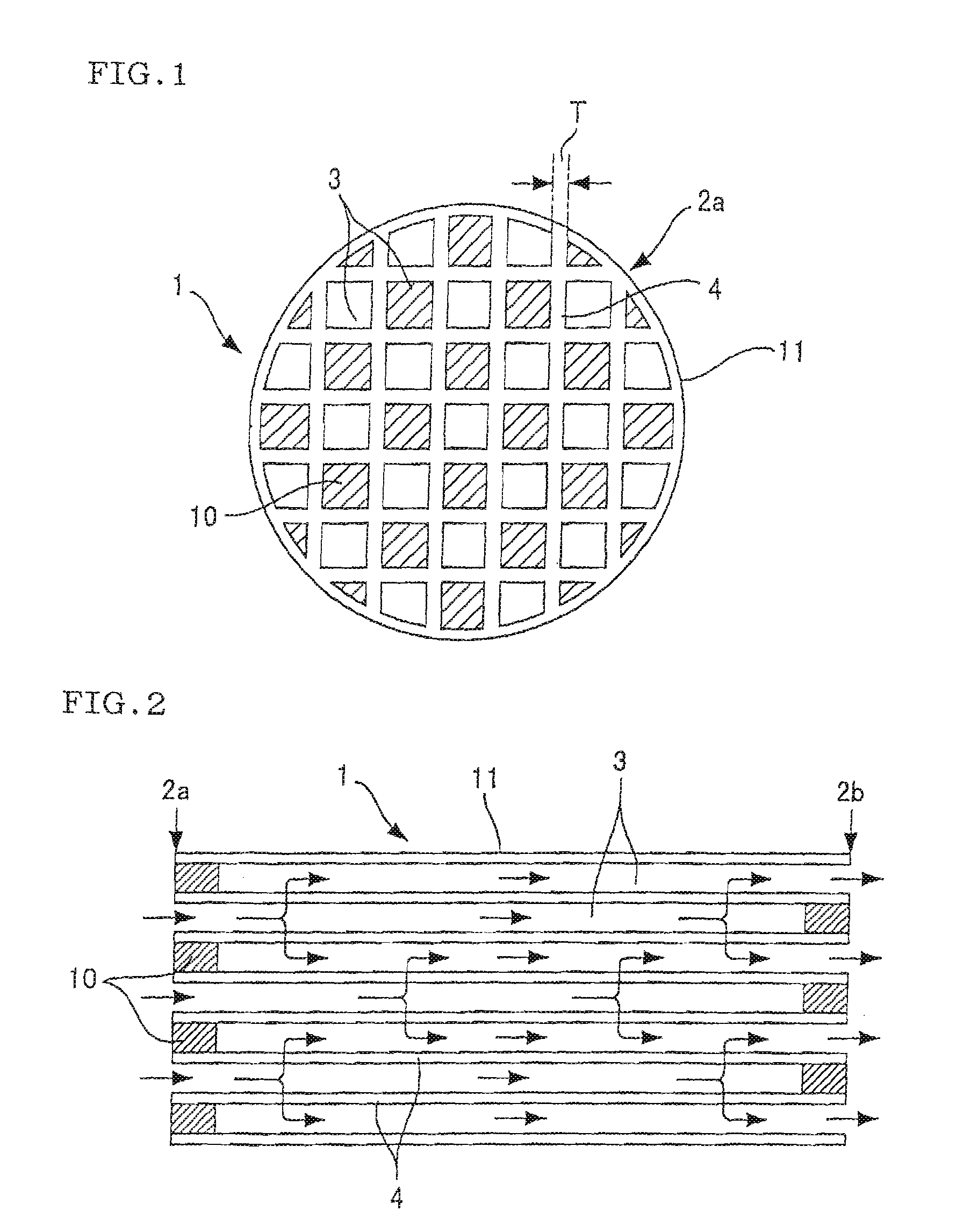
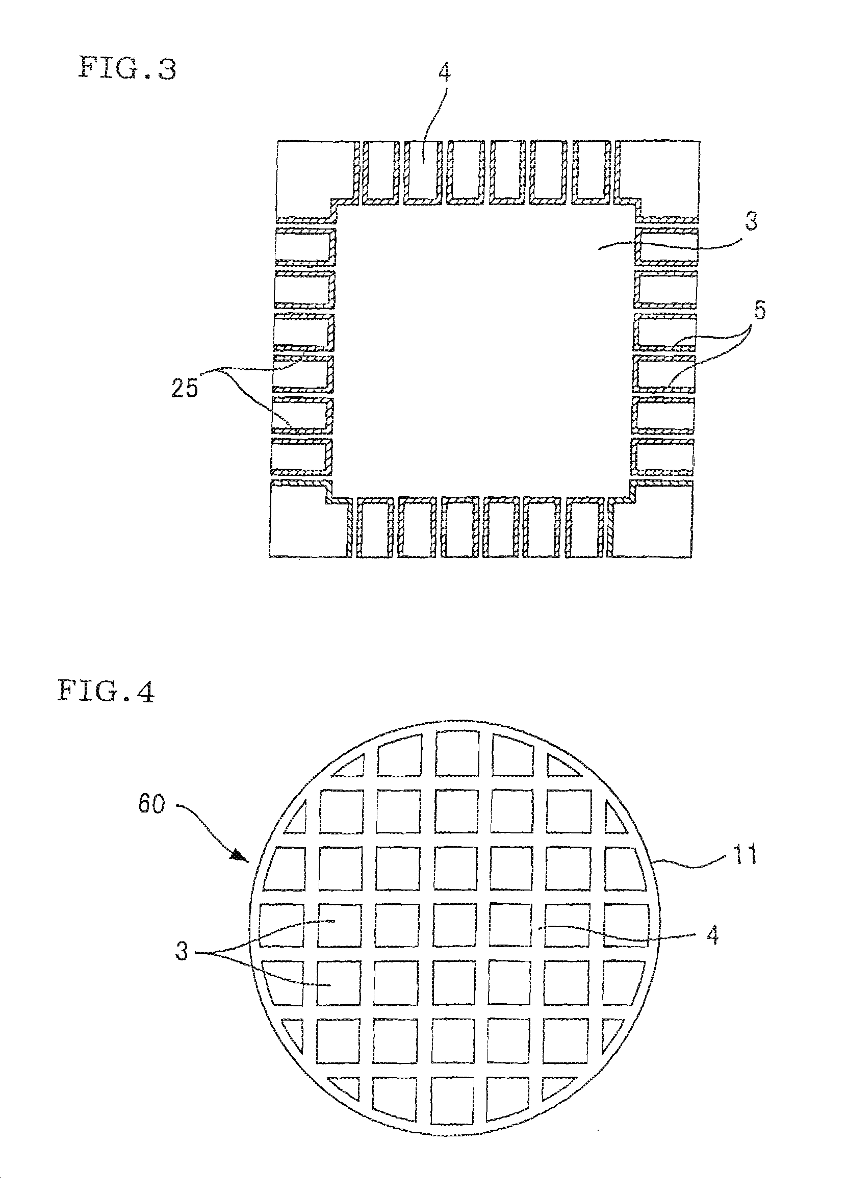
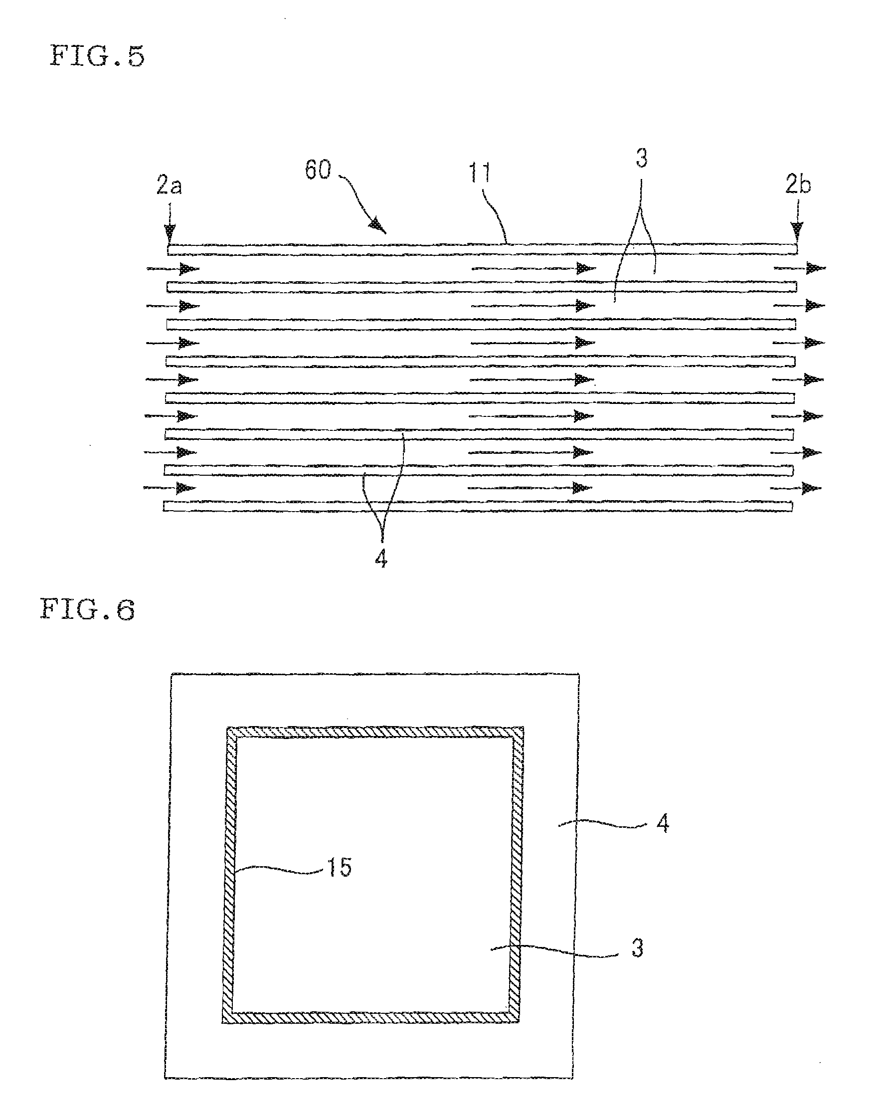
[0109]As the honeycomb structures for loading a catalyst layer thereon, there were prepared those each made of a material shown in Table 1 and having a cell structure, an average pore diameter and a permeability, shown in Table 1 (in Table 1, however, permeability data were shown only for representative Examples and Comparative Examples). The measurement methods for average pore diameter and permeability are described later. As to the external size of honeycomb structure, there were prepared two kinds for each Example and each Comparative Example, that is, a honeycomb structure of 5.66 in. (diameter)×6 in. (length) and a honeycomb structure of 1 in. (diameter)×2 in. (length). The former was named “honeycomb structure A” and the latter was named “honeycomb structure B”. Incidentally, in these honeycomb structures, each cell was plugged at either one end so that the cell ends were plugged alternately at each end face of honeycomb structure and that each end f...


PUM

PropertyMeasurementUnit
Fractionaaaaaaaaaa
Fractionaaaaaaaaaa
Fractionaaaaaaaaaa

Abstract

According to the present invention, there is provided a honeycomb catalytic structure comprising:
    • a honeycomb structure comprising porous partition walls having a large number of pores, disposed so as to form a plurality of cells extending between the two end faces of the honeycomb structure and plugging portions disposed at either one end of each cell, and
    • a catalyst layer containing a catalyst, supported at least on the inner surfaces of the pores of the honeycomb structure,
    • wherein the mass of the catalyst layer per unit volume (1 cm3) of the honeycomb structure (g/cm3) is 60% or less of the volume of pores per unit volume (1 cm3) of the honeycomb structure (cm3/cm3).

Description

TECHNICAL FIELD[0001]The present invention relates to a honeycomb catalytic structure which is suitably used for purification of to-be-purified components such as carbon monoxide (CO), hydrocarbons (HC), nitrogen oxides (NOx), sulfur oxides (SOx) and the like, contained in exhaust gases emitted from automobiles engines, construction equipments engines, and stationary engines for industries as well as combustion equipment, etc.; a precoated support for producing the above honeycomb catalytic structure; and a process for producing the above honeycomb catalytic structure.BACKGROUND ART[0002]Currently, catalytic material of honeycomb structure (honeycomb catalytic structure) is in use in order to purify the exhaust gases emitted from kinds of engines, etc. This honeycomb catalytic structure has a constitution in which a catalyst layer 15 is loaded on the surfaces of the partition walls 4 which form cells 3 as shown in FIG. 6. Further, as shown in FIGS. 4 and 5, the purification of exhau...

Claims


Application Information

Patent Timeline
IPC IPC(8): B01J21/04
CPCB01D46/2429Y02T10/20B01D2046/2437B01D2046/2496B01D2279/30B01J23/63B01J35/023B01J35/04B01J35/10B01J37/0036B01J37/0234F01N3/0222F01N2510/06F01N2510/0682B01D46/2466Y02T10/12B01D46/24492B01D46/2498
Inventor NODA, NAOMIMIYAIRI, YUKIOYAMADA, TOSHIO
Owner NGK INSULATORS LTD
Why Eureka
Try Eureka