Integrated Gaseous Fuel Delivery System

a gaseous fuel and integrated technology, applied in the direction of machines/engines, output power, electric control, etc., can solve the problems of high pressure connection, hydrogen leakage in the hydrogen system, etc., to reduce or limit the leakage of fuel, increase the cost, and limit the freedom of spatial design

Inactive Publication Date: 2008-06-12
FORD GLOBAL TECH LLC
View PDF10 Cites 5 Cited by
  • Summary
  • Abstract
  • Description
  • Claims
  • Application Information

AI Technical Summary

Benefits of technology

[0007]The inventors herein have recognized the need to reduce or limit fuel leakage and potential drawbacks with current approaches for a hydrogen or gas-based system. As described above, each coupling in a hydrogen system may be a potential hydrogen leakage point. Further, some current systems use intermediate containment areas in an attempt to control gaseous fuel leakage. However, dangerous gases may accumulate in the intermediate containment areas and a venting system may be needed to handle the leaked gases. The intermediate containment capsule, the venting system, and / or other aspects of such a system may increase cost and / or limit spatial design freedom. Furthermore, any fuel leakage may reduce overall fuel efficiency.
[0008]As an example, at least some of the issues associated with gaseous fuel leakage may be addressed by a fuel delivery system that includes limited connections at which fuel may leak from the system. As an example, a storage tank may be used to hold a gaseous fuel, and the fuel may be converted by a powerplant to energy that is useable to power a vehicle. The fuel stored in the tank may be delivered to the powerplant by an uninterrupted passage fluidically coupling the storage tank to the powerplant. In some embodiments, a pressure regulation system may be located interior the storage tank. The pressure regulation system may decrease or increase the pressure of the gaseous fuel so that the gaseous fuel is suitable for delivery to the powerplant.
[0009]In this manner, the number of connections intermediate the fuel tank and the powerplant may be limited, thus minimizing opportunities for gaseous fuel to leak from the system. Because the pressure regulation system is physically located within the storage tank, any leakage that occurs in the pressure regulation system may return to the storage tank. By using an integrated fuel delivery system, gas leakages may be reduced and fuel efficiency improved.

Problems solved by technology

Although hydrogen fuel systems may be an environmentally desired option over hydrocarbon systems, hydrogen systems may suffer from hydrogen leakage.
In particular, if hydrogen is stored as high pressure gas, high pressure connections (e.g., the first or second high pressure reducing regulators, fuel pressure sensing or quantity gauging, and / or any electrical or manual shutoff devices) may be susceptible to hydrogen leakage.
However, dangerous gases may accumulate in the intermediate containment areas and a venting system may be needed to handle the leaked gases.
The intermediate containment capsule, the venting system, and / or other aspects of such a system may increase cost and / or limit spatial design freedom.
Furthermore, any fuel leakage may reduce overall fuel efficiency.
In this manner, the number of connections intermediate the fuel tank and the powerplant may be limited, thus minimizing opportunities for gaseous fuel to leak from the system.

Method used


Image

  • Integrated Gaseous Fuel Delivery System
  • Integrated Gaseous Fuel Delivery System
  • Integrated Gaseous Fuel Delivery System

Examples


Embodiment Construction

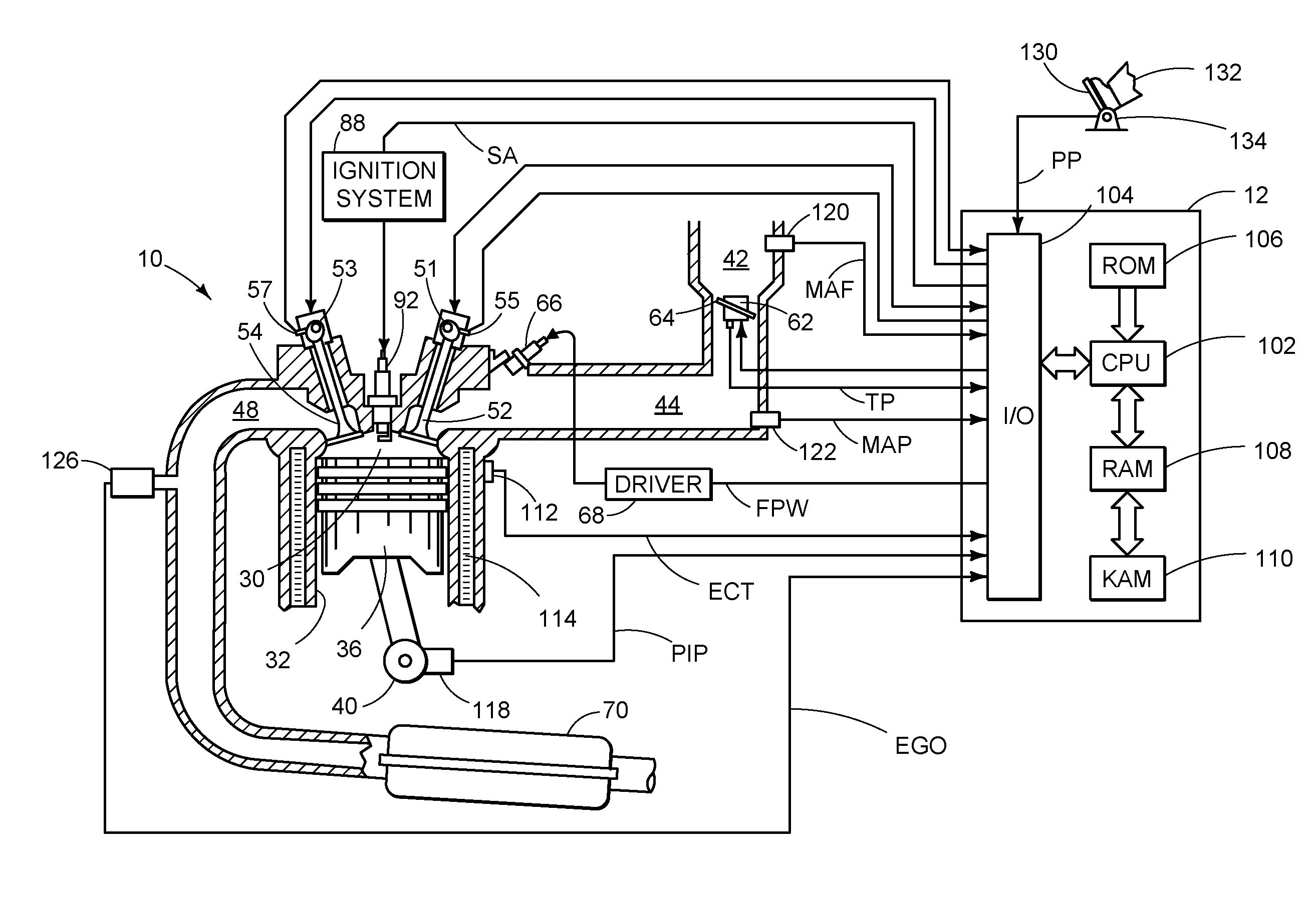
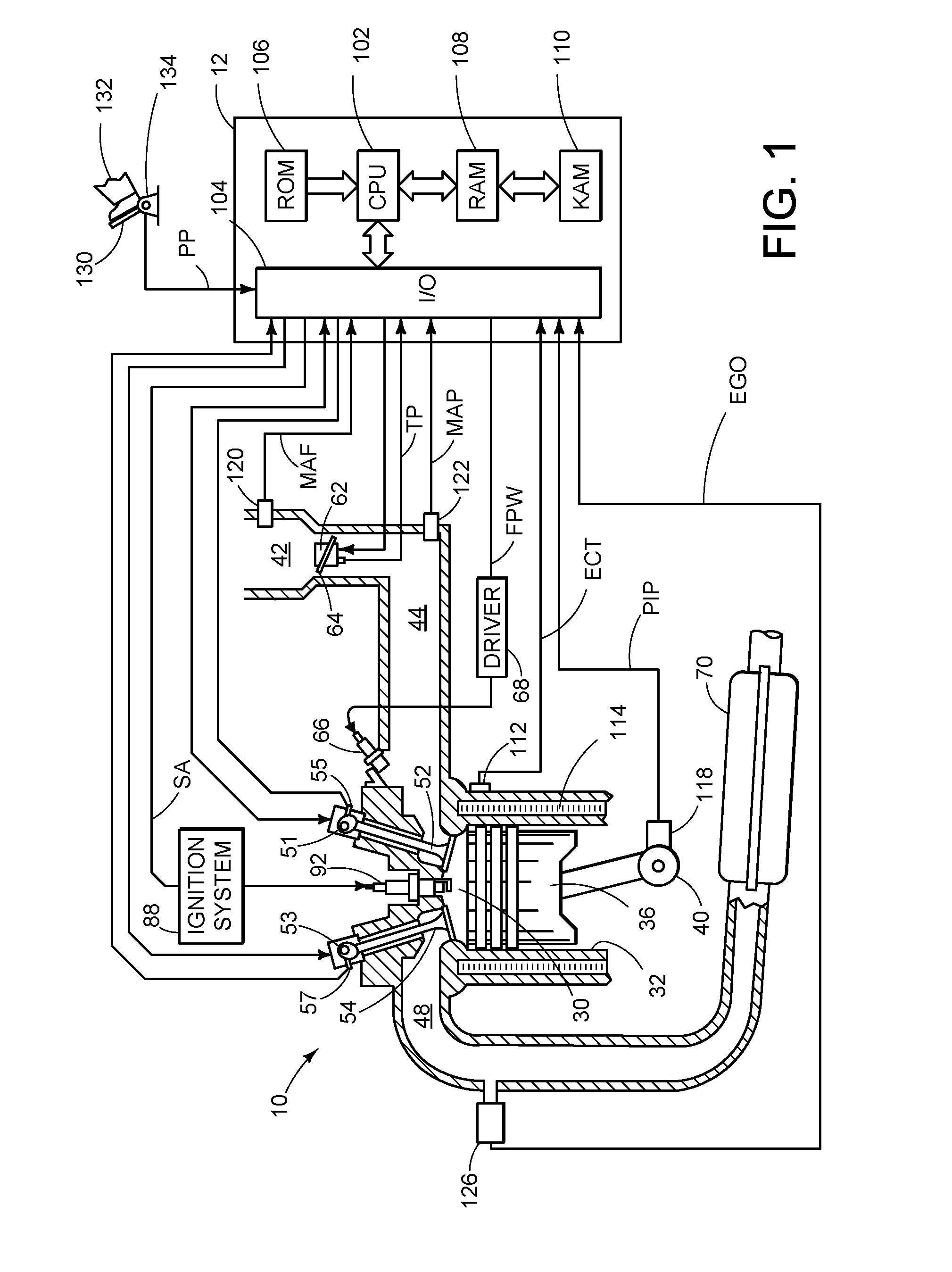
[0016]FIG. 1 is a schematic diagram showing one cylinder of multi-cylinder engine 10, which may be included in a propulsion system of an automobile. The configuration of engine 10 is merely exemplary, and the systems and methods described herein may be implemented in any other suitable engine. Moreover, as described, engine 10 may include a gaseous fuel system. Hydrogen gas is a nonlimiting example of a gaseous fuel that can be used with the fuel delivery system of the present disclosure. It should be noted that hydrogen may be pure hydrogen or it may be a mixture of hydrogen and another gas, such as another gaseous fuel. Further, in some examples, the gaseous fuel, e.g. hydrogen, may be used in combination or mixed with liquid fuel such as gasoline or diesel fuel. Thus, while the examples herein describe a hydrogen fuel delivery system, other gaseous fuels systems may be substituted for or used in combination with hydrogen, if desired.

[0017]Engine 10 may be controlled at least part...


PUM


Abstract

An integrated gaseous fuel delivery system is provided. The system includes a storage tank to hold a gaseous fuel and a pressure regulation system disposed interior the storage tank and configured to regulate a pressure of gaseous fuel delivered from the storage tank.

Description

FIELD[0001]The present application relates to systems, apparatus and methods for an integrated gaseous fuel delivery system.BACKGROUND AND SUMMARY[0002]In an attempt to reduce emissions, efforts have been made to utilize substantially carbon-free hydrogen as a combustion fuel instead of hydrocarbons. When hydrogen (H2) is used as the fuel, there is not a substantial amount of HC, CO, or CO2 emissions, because the fuel does not include carbon that can be turned into HC, CO, or CO2. Therefore, hydrogen fuel is currently viewed as a potentially good fuel choice for environmentally clean internal combustion engines.[0003]Hydrogen can also be used as an energy source by a variety of other devices. For example, a fuel cell can convert hydrogen into electrical energy using an environmentally clean reaction.[0004]Although hydrogen fuel systems may be an environmentally desired option over hydrocarbon systems, hydrogen systems may suffer from hydrogen leakage. Specifically, hydrogen is a sma...

Claims


Application Information

Patent Timeline
Patent Type & Authority Applications(United States)
IPC IPC(8): F02M25/10
CPCF02D13/0203F02D41/0027F02D2250/31Y02T10/32F02D19/022F02M21/0206F02M21/0221F02M21/0275F02M21/0293Y02T10/30
Inventor KOTWICKI, ALLANLEWIS, DONALD J.BOYER, BRAD
Owner FORD GLOBAL TECH LLC
Why Eureka
Try Eureka