Optical modeling apparatus

a technology of optical modeling and modeling apparatus, which is applied in the field of optical modeling apparatus, can solve the problems of enormous modeling time, no better than 50 microns of accuracy of known three-dimensional modeling methods and three-dimensional modeling apparatuses, and the original use of no better than 50 microns, so as to reduce the strength and shorten the time

Inactive Publication Date: 2008-07-03
SONY CORP
View PDF0 Cites 41 Cited by
  • Summary
  • Abstract
  • Description
  • Claims
  • Application Information

AI Technical Summary

Benefits of technology

[0021]According to the embodiment of the present invention described above, each hardened layer is formed by using the light beam that is scanned by the scanning device and the light that is spatially modulated by the spatial light modulator to harden the light curable resin, thus forming a high-resolution three-dimensional model in a short time. In addition, using the exposure position adjuster to move the light that is transmitted by the spatial light modulator inhibits a decrease in strength due to the influence of an unexposed portion, thus making it possible to form a high-strength three-dimensional model.

Problems solved by technology

However, the degree of precision of the known three-dimensional modeling methods and three-dimensional modeling apparatuses, due to the purposes for which they were originally used, is generally no better than around 50 microns.
When an effort is made to improve the precision to the range of several microns, for example, an enormous amount of modeling time is required, and it is difficult to produce a model of a large region.
In other words, it is extremely difficult to produce a comparatively large model with high resolution.
However, there is a limit to the intensity of the light source, and because the shape is basically plotted by scanning with a single light beam, an extremely long period of time is required in order to expose a comparatively large region to the light beam so that a hardened layer with a large surface area can be formed.
In addition, in the known modeling apparatuses, the configurations of the optical systems limit the scanning range of the light beam, which imposes a limit on the formation of a hardened layer for a large region.

Method used


Image

  • Optical modeling apparatus
  • Optical modeling apparatus
  • Optical modeling apparatus

Examples


Embodiment Construction

[0044]Hereinafter, a preferred embodiment of the present invention will be described in detail with reference to the appended drawings. Note that, in this specification and the appended drawings, structural elements that have substantially the same function and structure are denoted with the same reference numerals, and repeated explanation of these structural elements is omitted.

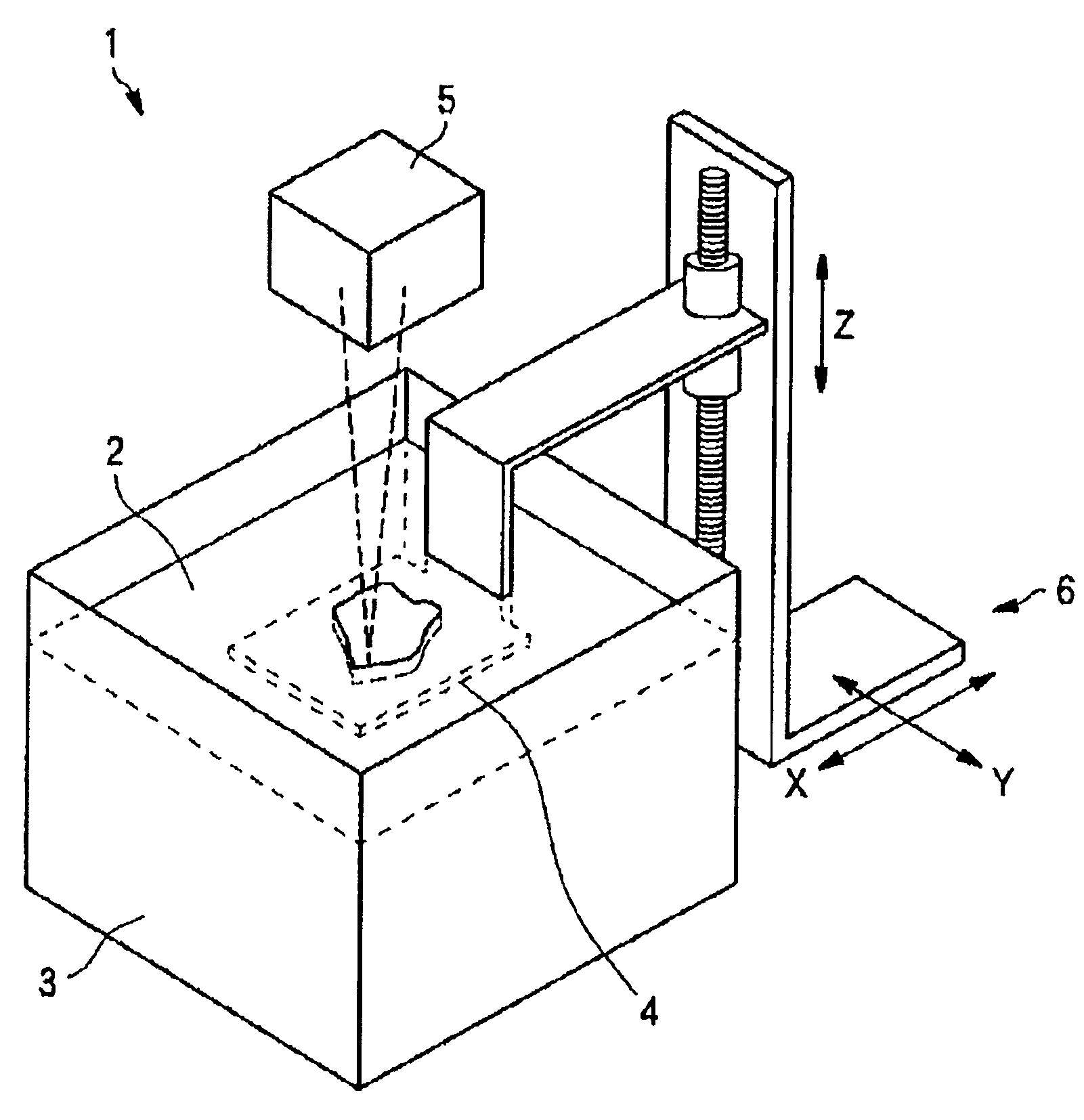
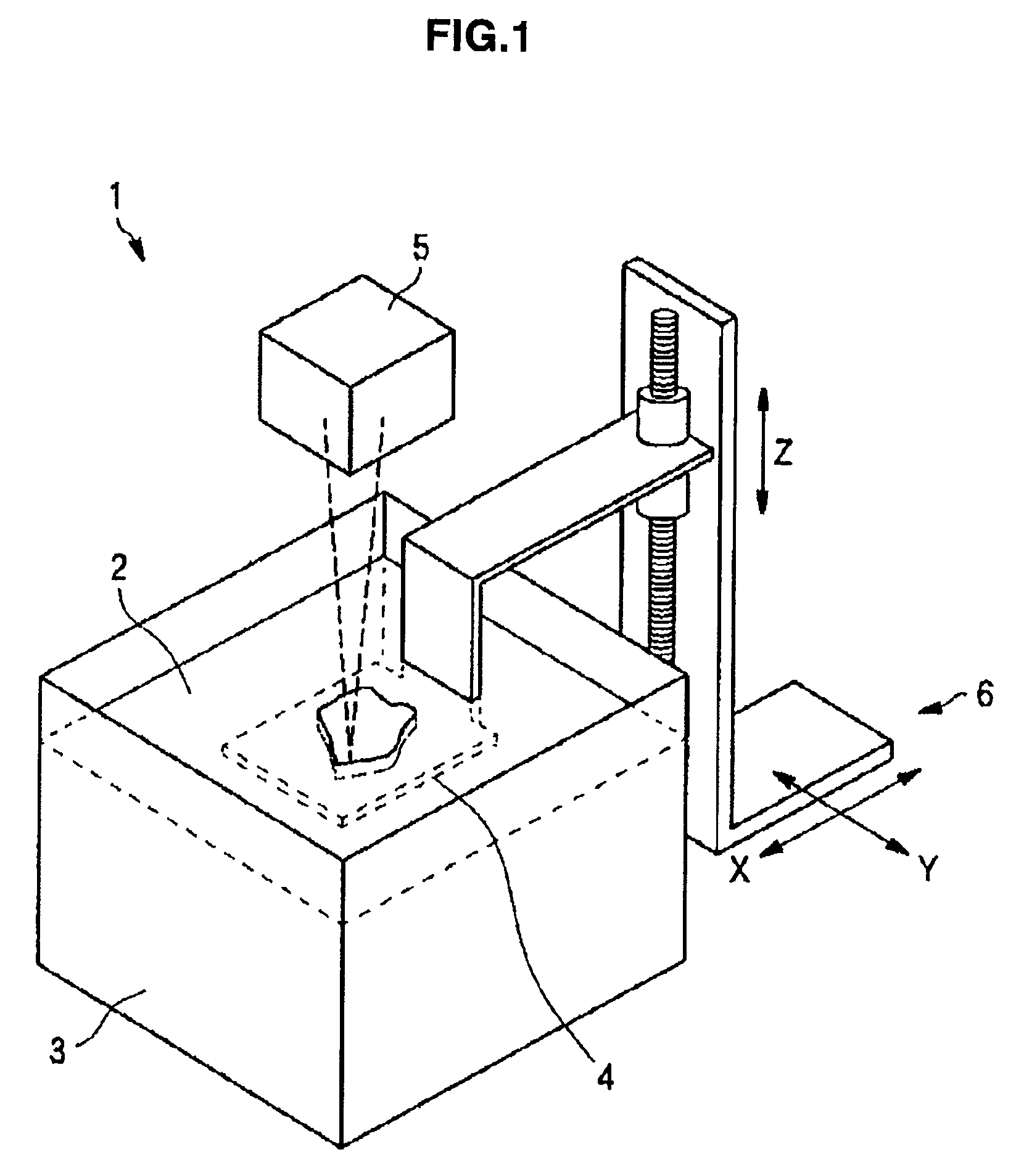
[0045]An optical modeling apparatus 1 according to an embodiment of the present invention, as shown in FIG. 1, is an optical modeling apparatus that forms a series of hardened layers by exposing a light curable resin to light, accumulating the layers to form a model of a desired shape. Note that the embodiment explained below uses a liquid ultraviolet curable resin as the light curable resin, but the present invention is not limited to using a liquid resin. For example, a resin film may also be used. Moreover, the present invention is not limited to using an ultraviolet curable resin. That is, any material ...


PUM

PropertyMeasurementUnit
thicknessaaaaaaaaaa
focal lengthaaaaaaaaaa

Abstract

There is provided an optical modeling apparatus that forms a model of a desired shape by sequentially forming hardened layers by irradiating a light curable resin with light. The apparatus includes a first light source that emits a light beam for plotting on the resin, a scanning device that scans the light beam from the first light source over the resin, a second light source that emits light that irradiates one fixed region of the resin at a time, a spatial light modulator that spatially modulates the light from the second light source and blanket-exposes a specified region of the resin, and an exposure position adjuster that moves, in at least one direction, the light from the spatial light modulator. The light beam from the scanning device and the light from the spatial light modulator form each hardened layer.

Description

CROSS REFERENCE TO RELATED APPLICATION[0001]The present invention contains subject matter related to Japanese Patent Application JP 2006-356003 filed in the Japan Patent Office on Dec. 28, 2006, the entire contents of which being incorporated herein by reference.BACKGROUND OF THE INVENTION[0002]1. Field of the Invention[0003]The present invention relates to an optical modeling apparatus that forms a resin model of a desired shape by exposing a light curable resin such as an ultraviolet curable resin or the like to light to form a hardened layer, then stacking the hardened layers to form the model.[0004]2. Description of the Related Art[0005]In recent years, a technique called rapid prototyping has become a focus of attention in many manufacturing environments. Rapid prototyping uses three-dimensional shape data that is input from a CAD device to create a three-dimensional model of a target shape without doing any machining or the like.[0006]Methods that are known as rapid prototypin...

Claims


Application Information

Patent Timeline
Patent Type & Authority Applications(United States)
IPC IPC(8): B29D11/00
CPCB29C67/0066B29C67/0062B29C64/124B29C64/135B33Y30/00B33Y50/02
Inventor KIHARA, NOBUHIROYAMAMOTO, MASANOBU
Owner SONY CORP
Why Eureka
Try Eureka