Oil well completion tool having severable tubing string barrier disc

US20080271883A1Inactive Publication Date: 2008-11-06FIKE CORP

Image

  • Oil well completion tool having severable tubing string barrier disc
  • Oil well completion tool having severable tubing string barrier disc
  • Oil well completion tool having severable tubing string barrier disc

Examples


Embodiment Construction

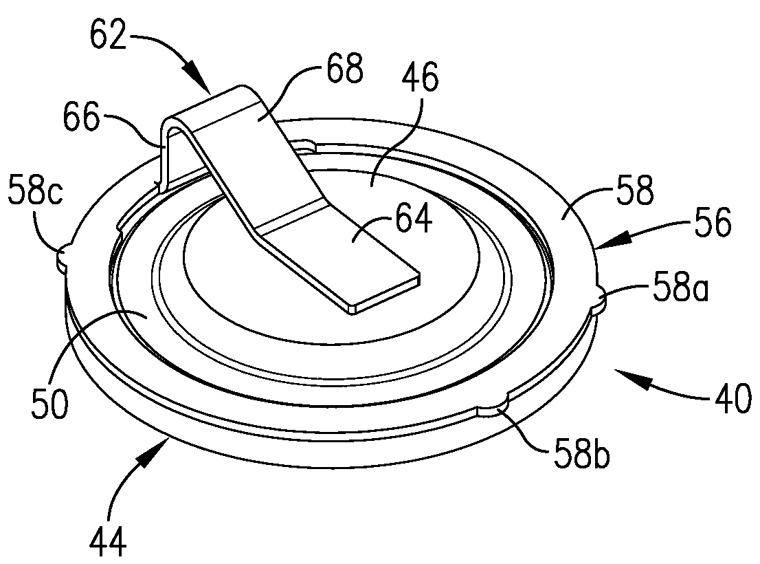
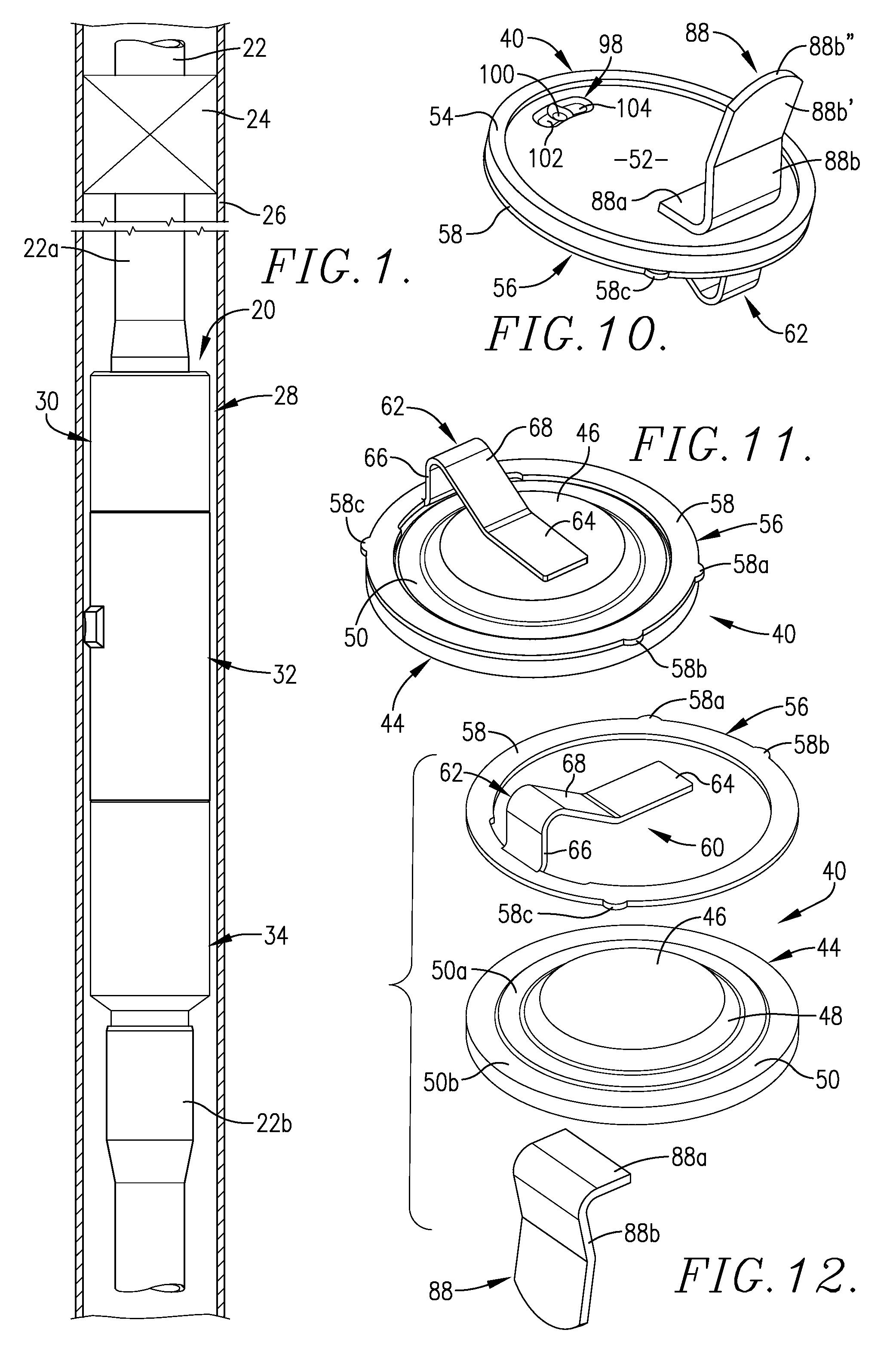
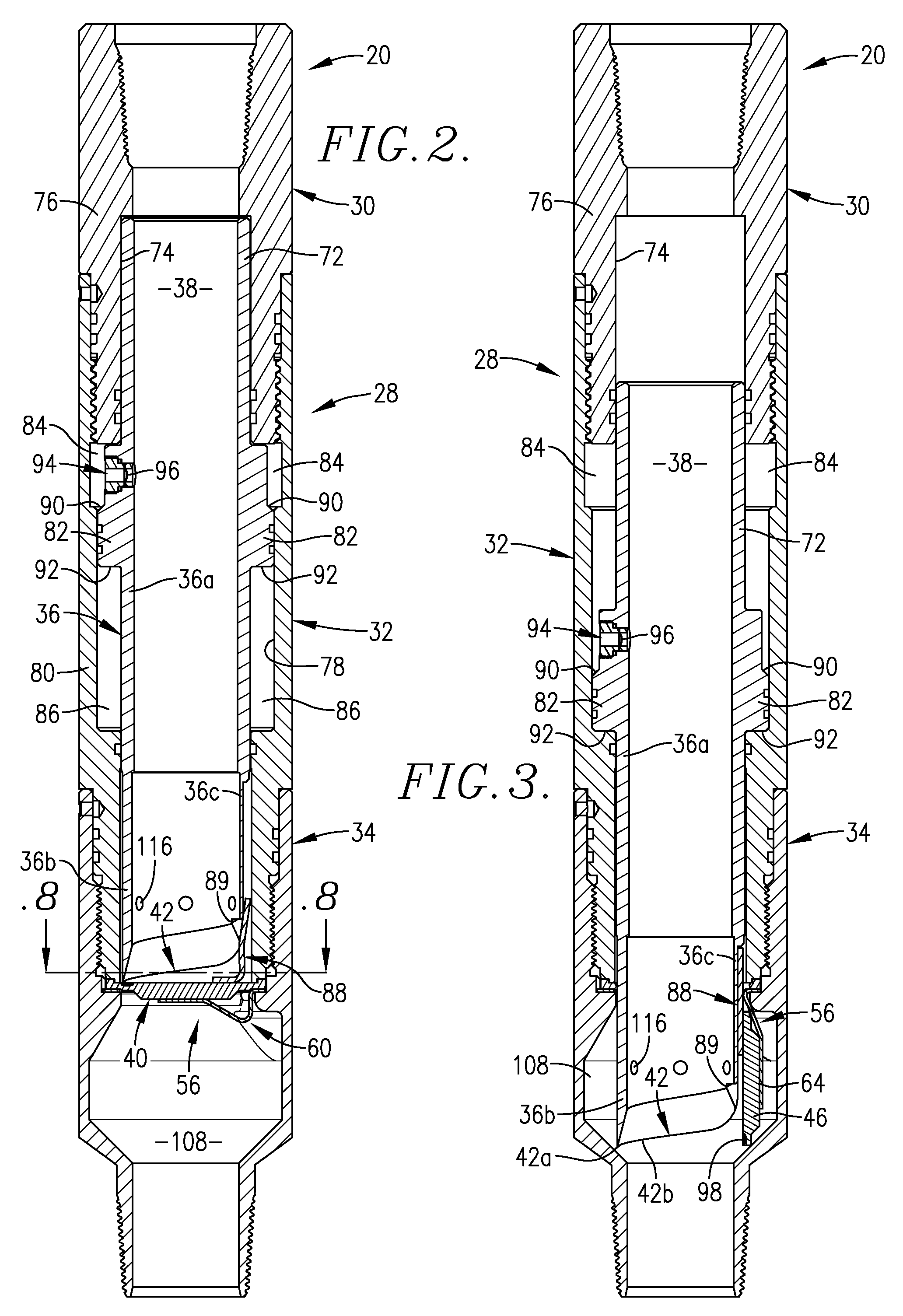
[0045]An oil well completion tool 20 in accordance with one preferred embodiment of this invention, shown in elevation in FIG. 1 of the drawings, is depicted as being mounted in a multiple-section tubing string 22 below a diagrammatically-illustrated packer 24 within oil well casing 26. The tool 20 comprises a tubular assembly 28 having an upper threaded box sub 30 adapted to receive a threaded end of the tubing section 22a. The housing 32 of assembly 28 is threadably connected to top sub 30 and interposed between sub 30 and lower threaded pin sub 34. The pin sub 34, threadably joined to housing 32, is adapted to be threaded into a section 22b of tubing string 22. A shear cylinder unit 36 is shiftably mounted in housing 32 for movement axially of the main passage 38 of tool 20. A severable plug, broadly designated 40, is mounted between adjacent ends of housing 32 and lower sub 34. The plug 40 in its normal position, blocks main passage 38 of tool 20. Plug 40 is preferably of a meta...


PUM


Abstract

An oil well completion tool having a tubular assembly defining an elongated main passage is adapted to be connected to a multiple-section tubing string within an oil well casing. A severable plug is mounted in the tubular assembly in normal blocking relationship to the passage. A movable shear cylinder unit has a plug-severing edge operable to sever an entire central segment of the plug from a remaining peripheral portion thereof. Separate hinge structure has an elongated U-shaped leg portion connected to the central segment of the plug. The leg portion of the hinge structure, which undergoes elongation, is operable to retain the severed central segment of the plug in the main passage while allowing the central segment of the plug to bodily shift independent of and in a direction away from the peripheral portion of the plug. The severed central segment is received in a recess therefor in the tubular assembly wall structure in order to prevent interference of the severed central plug segment with the main passage.

Description

CROSS-REFERENCE TO RELATED APPLICATION[0001]This application is a continuation-in-part of U.S. patent application Ser. No. 11 / 744,605, filed May 4, 2007, incorporated by reference herein.BACKGROUND OF THE INVENTION[0002]1. Field of the Invention[0003]This invention relates to an oil well completion tool that is adapted to be interposed in a multiple-section tubing string within an oil well casing, most usually above another oil well tool, such as a packer. The completion tool allows the tubing string to be blocked, for example, in order to allow setting of a packer or the like, and to thereafter be fully opened for production from the well.[0004]2. Description of the Prior Art[0005]Typically when oil or gas wells are drilled in hydrocarbon-bearing formations, the bore hole is thereafter isolated from the surrounding formation by a string of interconnected, relatively large diameter pipe sections, generally referred to as a well casing. The casing sections may, for example, be about ...

Claims


Application Information

Patent Timeline
06 Nov 2008
Publication
US20080271883A1
IPC
E21B33/12; E21B34/14
CPC
E21B34/063; Y10T137/1699; Y10T137/1759; Y10T137/1744
Inventors
BARTON, JOHN A.; BURRIS, MARK