Dry to the touch vapor hydration sleeve

a technology of vapor hydration and sleeve, which is applied in the direction of catheters, coatings, other medical devices, etc., can solve the problems of increasing the risk of infection, affecting the safety of catheter assembly,

Inactive Publication Date: 2015-10-29
HOLLISTER INCORPORAED
View PDF0 Cites 14 Cited by
  • Summary
  • Abstract
  • Description
  • Claims
  • Application Information

AI Technical Summary

Benefits of technology

[0036]FIG. 16 is a side elevational view illustrating a funnel end of the catheter engaged with an opening at the introducer tip

Problems solved by technology

First, when the proximal insertion end of the catheter is introduced into the urethra it may pick up microorganisms that are likely to be prevalent in the distal portion of the urethra.
These microorganisms are often carried by the proximal insertion end of the catheter into the bladder as it is fully inserted, thereby increasing the risk of infection.
Second, the handling of the catheter by the user may also introduce microorganisms onto the surface of the catheter which can cause infection after catheter insertion.
F

Method used


Image

  • Dry to the touch vapor hydration sleeve
  • Dry to the touch vapor hydration sleeve
  • Dry to the touch vapor hydration sleeve

Examples


first embodiment

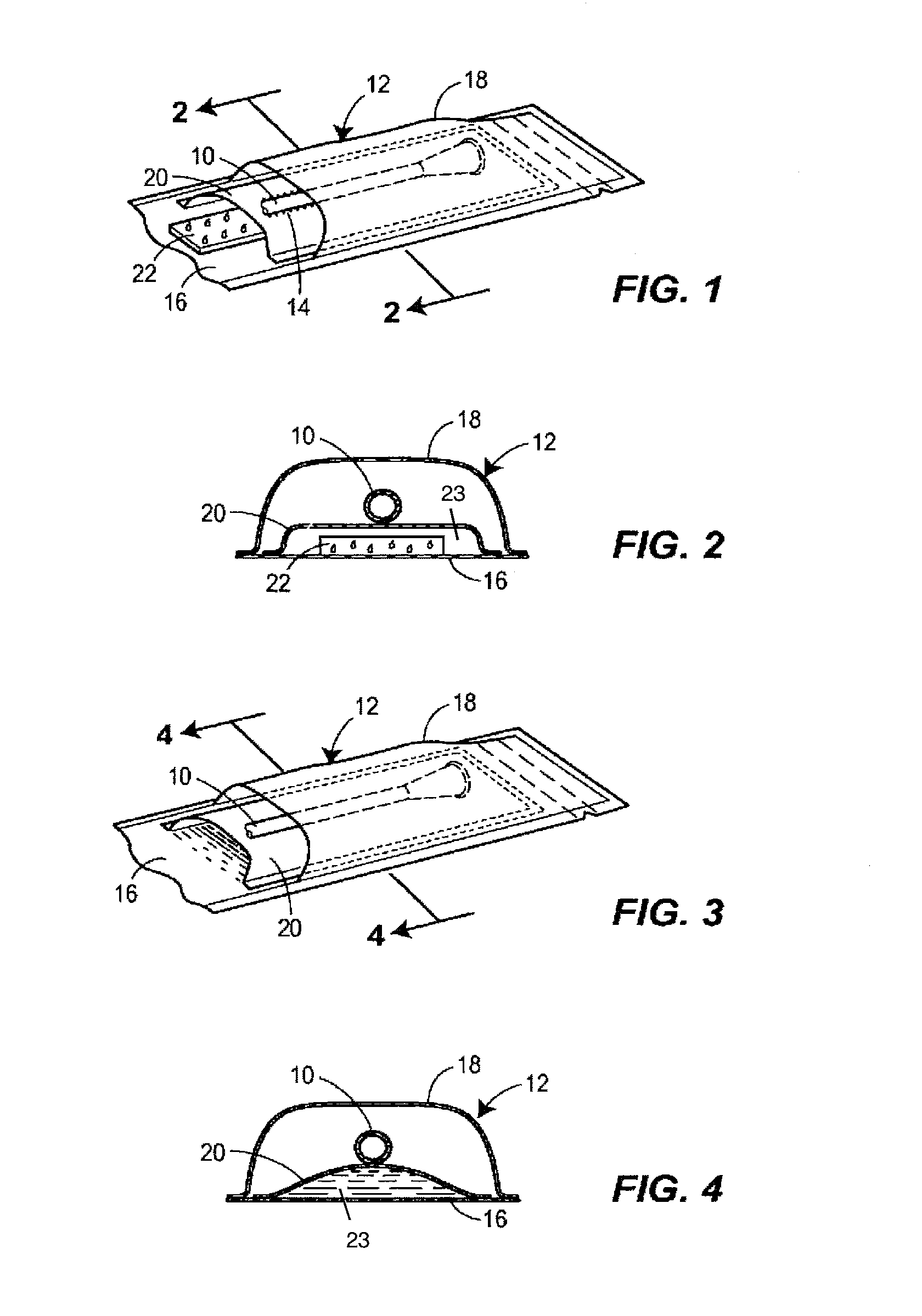
[0046]In a first embodiment, illustrated in FIGS. 1 and 2, a wicking element 22 is provided in the region 23 between the liquid water impermeable, water vapor permeable membrane 20 and the inner surface of the at least one of the first and second sleeve walls 16, 18 to which the water vapor permeable membrane 20 is sealed (i.e., the inner surface of the sleeve 12). Water in liquid phase is added to the wicking element 22, which evenly disperses liquid confined between the water vapor permeable membrane 20 and the inner surface of the sleeve 12. The catheter 10 is provided in a region of the sleeve 12 that is on an opposite side of the water vapor permeable membrane 20 from the wicking element 22.

[0047]In this first embodiment, the water vapor permeable membrane 20, together with the wicking element 22, serve as a liquid flow interfering element disposed between the sleeve 12 and the insertable portion of the catheter 10 in a manner that prevents sufficient direct liquid contact with...

sixth embodiment

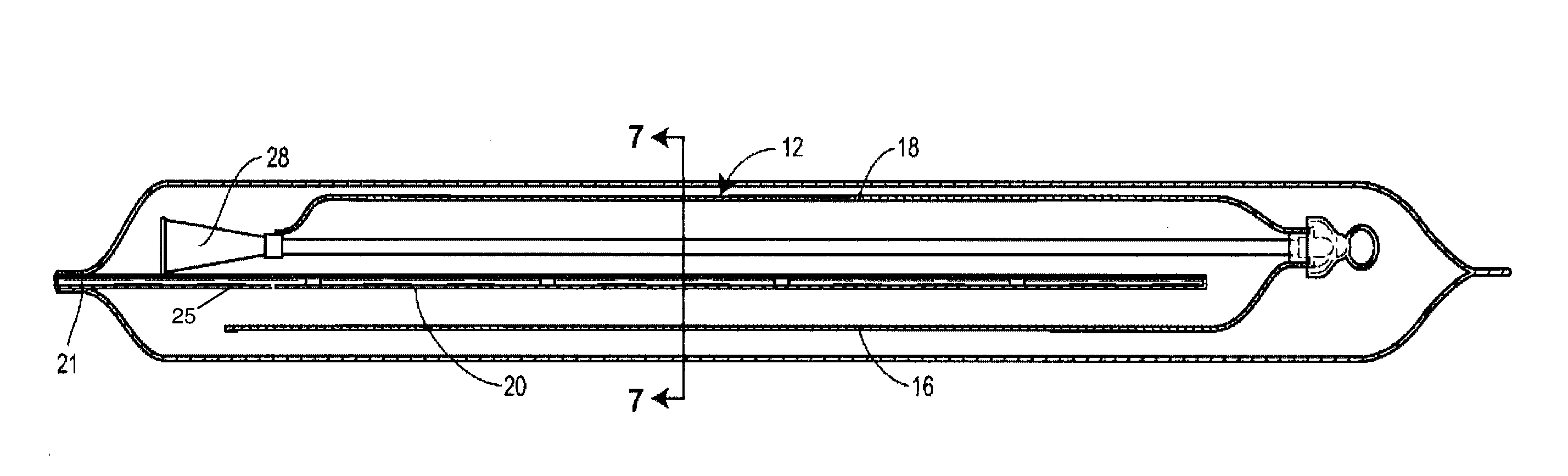
[0056]Turning now to FIGS. 18 and 19, a sixth embodiment is illustrated in which the entire insertable portion of a catheter 10 having a hydrophilic coating 14 is enclosed in a sleeve-like membrane 21 that forms an inner sleeve covering at least the insertable portion. The sleeve-like membrane 21 being a water vapor permeable polymer such as polyurethane or polyester, with a moisture vapor permeability greater than 300 g / m2 / day, 500 g / m2 / day, 1000 g / m2 / day, 2000 g / m2 / day or preferably greater than 3000 g / m2 / day. The sleeve-like membrane 21, which is liquid impermeable, is heat sealed to the collar 40 of a funnel 28 of the catheter 10. The sleeve-like membrane 21 is enclosed in a liquid and water vapor impermeable outer sleeve 42. The outer sleeve 42 is preferably made of polymeric films with a water permeability in the range of 0.1-10 g / m2 / day. In this embodiment, like the sleeve-like membrane 21, the outer sleeve 42 is sealed to the collar 40 of the funnel 28. Prior to sealing the ...


PUM

PropertyMeasurementUnit
Acoustic impedanceaaaaaaaaaa
Water vapor permeabilityaaaaaaaaaa
Flow rateaaaaaaaaaa

Abstract

A package for a hydrophilic coated catheter includes a sleeve with liquid water impermeable and water vapor impermeable walls. A liquid flow interfering element, such as a liquid water impermeable, vapor permeable membrane is provided within the sleeve. The sleeve may include a wicking element that is isolated from the catheter. Liquid water is provided on one side of the liquid flow interfering element. As the liquid water changes phase to a vapor, the vapor permeates through the liquid flow interfering element and activates the hydrophilic coating. The sleeve is collapsible during manipulation of the catheter through the wall of the sleeve so as to advance the catheter through an insertion tip to facilitate urethral insertion, with the exterior of the sleeve walls remaining dry to the touch. A funnel end of the catheter may remain in communication with the sleeve, such that the sleeve may be used to direct the flow of urine.

Description

RELATED APPLICATION[0001]This application claims the benefit of and priority to U.S. Provisional Patent Application Ser. No. 61 / 725,282, filed Nov. 12, 2012, the contents of which are incorporated by reference herein.FIELD OF THE DISCLOSURE[0002]The present disclosure is generally directed to a catheter assembly having a catheter shaft with a hydrophilic outer surface and, more particularly, to a catheter assembly having a protective sleeve that provides a barrier through which the catheter may be gripped / manipulated for inserting the catheter through the urethra and wherein, at point of use, the protective sleeve is dry to the touch.BACKGROUND OF THE DISCLOSURE[0003]Catheter assemblies are a good option for many users who suffer from various abnormalities of the urinary system. A common situation is where single use, individually packaged, sterile ready-to-use catheters are utilized. An important criterion for single use, ready-to-use products is that they be entirely user-friendly...

Claims


Application Information

Patent Timeline
IPC IPC(8): A61M25/00A61M25/01
CPCA61M25/002A61M25/0045A61M25/0111A61M2210/1089A61M2025/0062A61M2025/0098A61M2202/0496A61M2025/0047A61M2210/1096
Inventor ROSTAMI, SHAMSEDINFITZPATRICK, JAMES J.CARTER, ENDA F.MURRAY, MICHAEL G.O'FLYNN, PADRAIG M.HENRY, JEROME A.MORAN, MARTIN T.FOLEY, ADAM J.
Owner HOLLISTER INCORPORAED
Why Eureka
Try Eureka