Eureka AIR delivers breakthrough ideas for toughest innovation challenges, trusted by R&D personnel around the world.

Oil well completion tool having severable tubing string barrier disc

a technology of severable tubing and barrier disc, which is applied in the direction of sealing/packing, functional valve types, and borehole/well accessories, etc., can solve the problems of time-consuming operation, associated risks, and impracticality of mechanical packers

Inactive Publication Date: 2009-05-19
FIKE CORP
View PDF9 Cites 12 Cited by
  • Summary
  • Abstract
  • Description
  • Claims
  • Application Information

AI Technical Summary

Benefits of technology

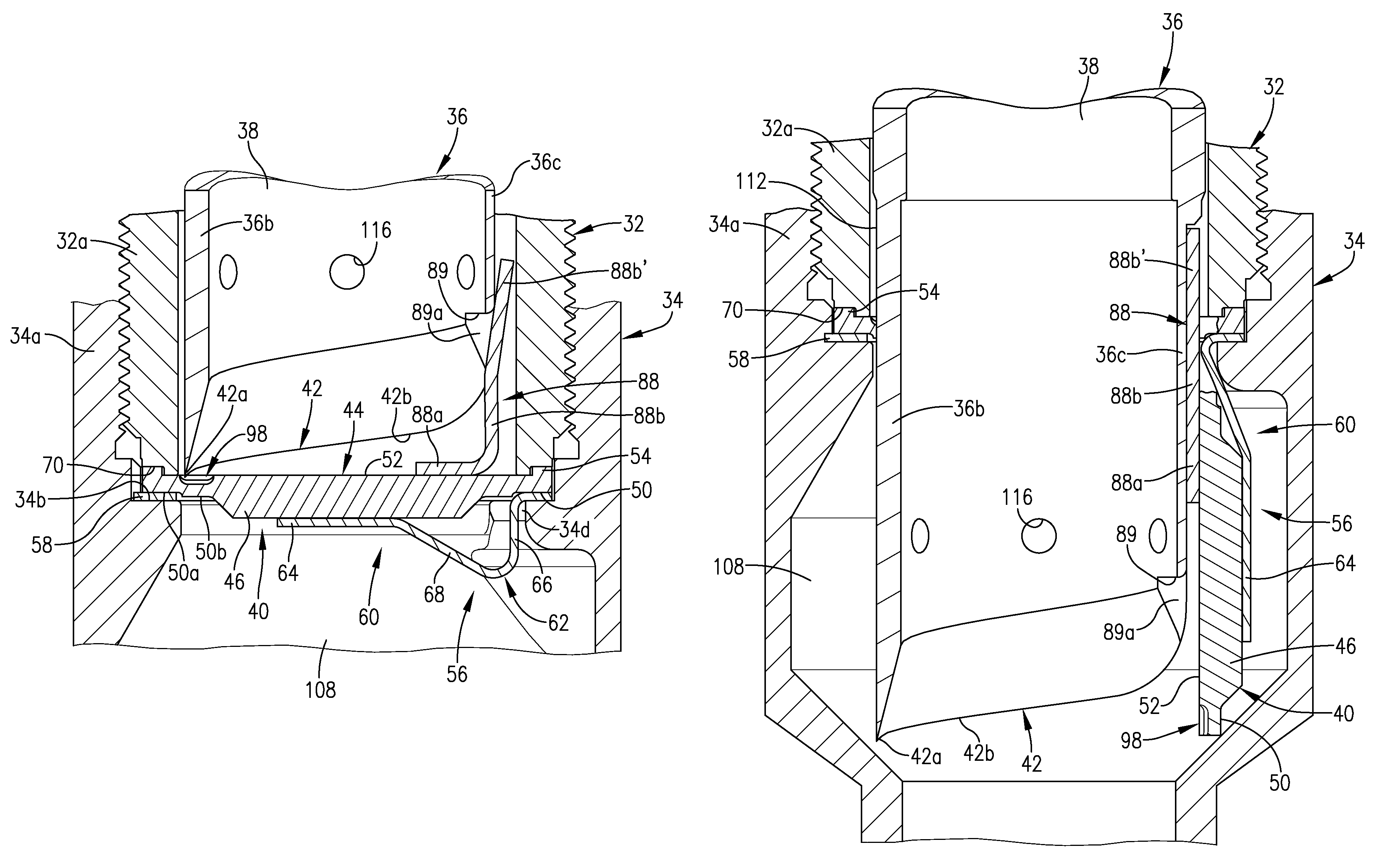
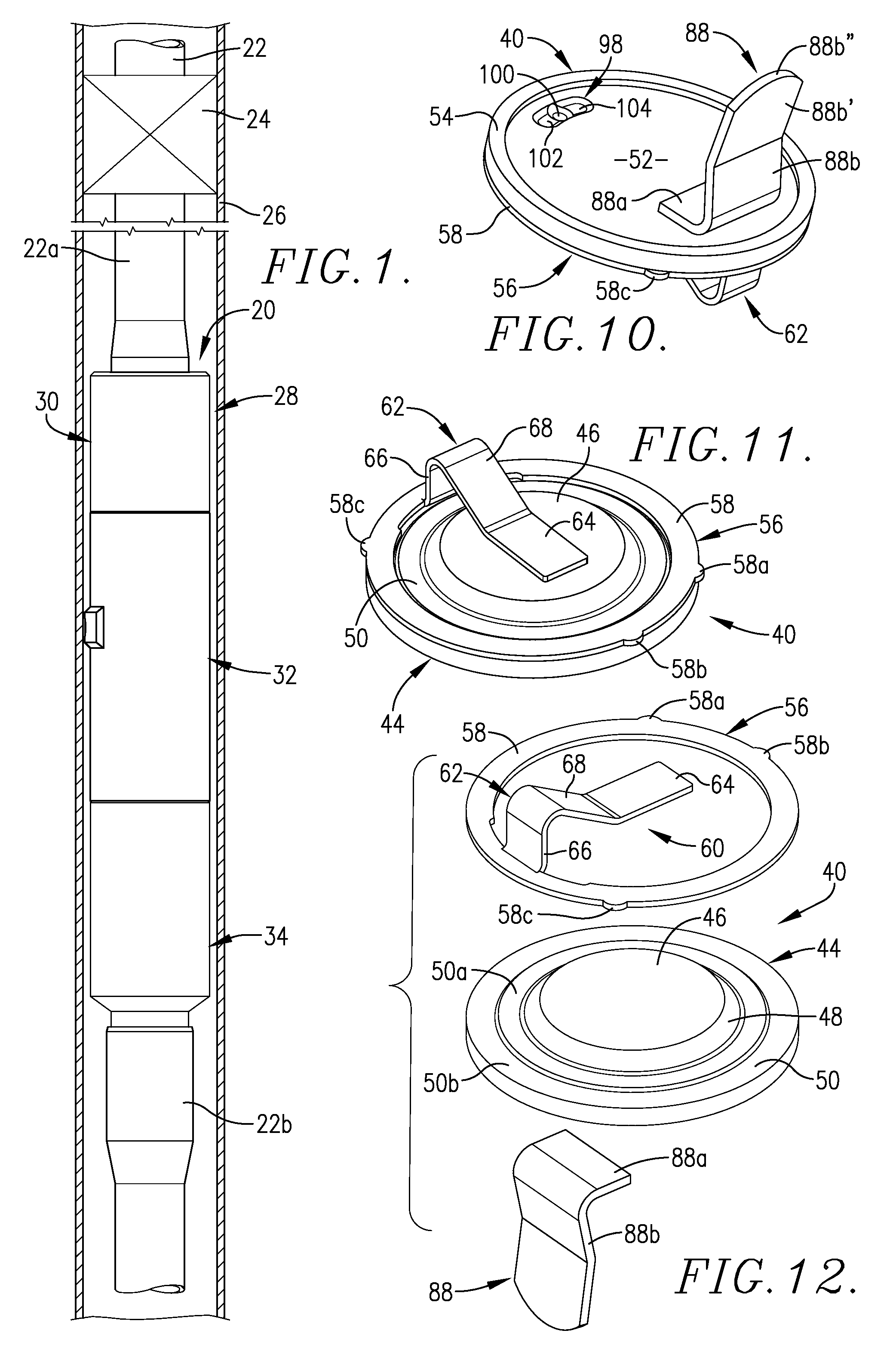
[0018]The oil well completion tool of this invention overcomes the problems presented by previously available tools. The tool includes a tubular assembly defining an elongated axially-extending main passage with a severable plug being mounted in the tubular assembly in normal blocking relationship to the axial passage. A movable shear cylinder unit within the tubular assembly has a plug-severing edge operable to sever an entire central segment of the plug from the remaining peripheral portion thereof when the shear cylinder unit is moved through a plug-severing displacement. Separate elongated hinge structure within the assembly has an inner elongated leg portion that is secured to the central segment of the plug facing the shear cylinder unit and an outer leg portion joined to an annular member connected to the peripheral portion of the plug. The elongated leg portion of the hinge structure, which is operable by virtue of its connection to the annular member, to retain the plug in the main body of the assembly after severing of the central segment thereof. The hinge structure allows the severed central plug segment to bodily shift independent of and in a direction away from the remaining peripheral annular portion of the plug. An L-shaped tab is provided on the periphery of the central section of the plug opposite the hinge structure. The tab, which is received in a cutout in the plug-severing edge of the shear cylinder, maintains the alignment of the leading edge portion of the shear cylinder with the central segment of the plug.
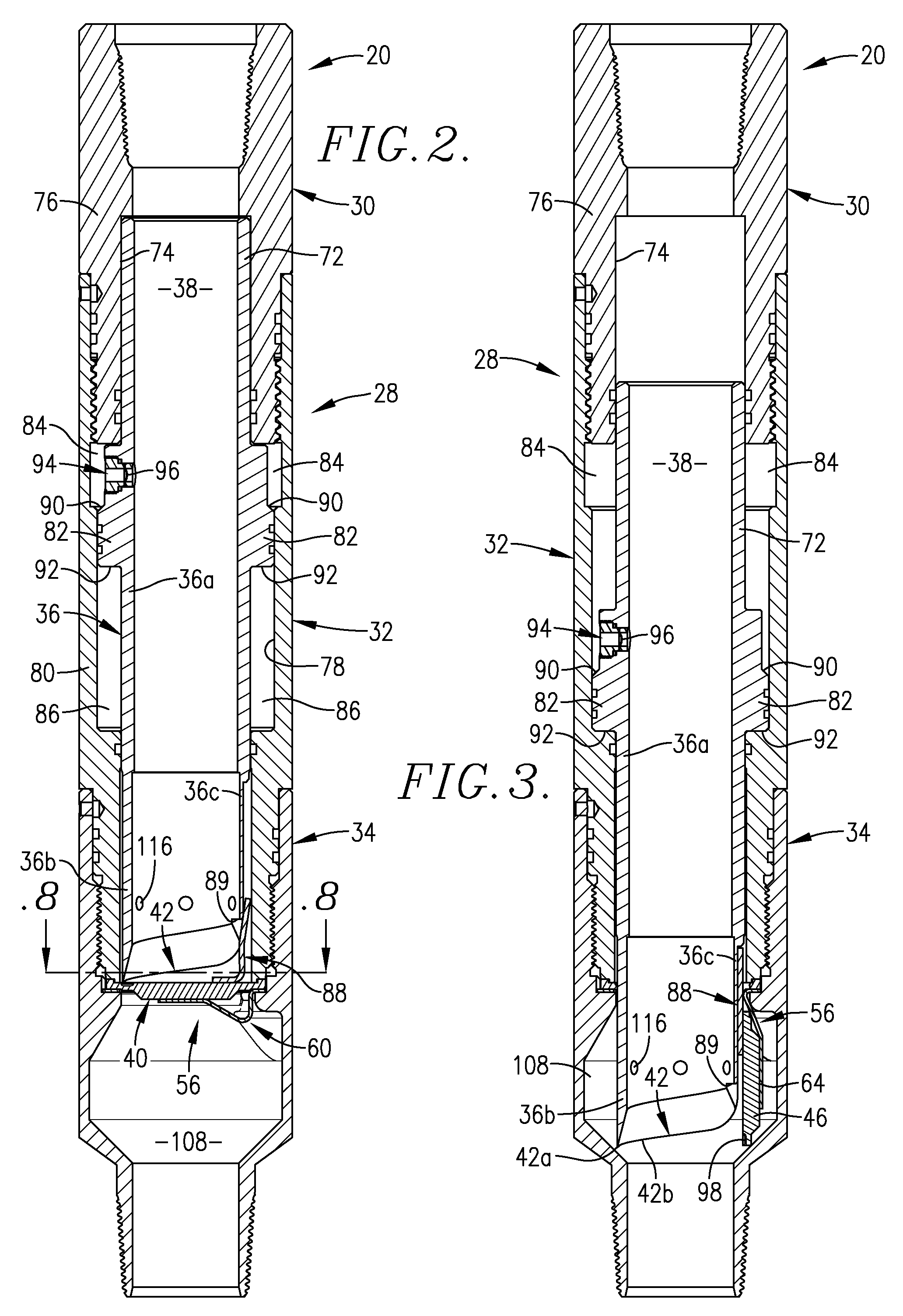
[0019]The severable blocking plug is preferably mounted in the tubular assembly of the tool between a bottom sub and a housing connected to a top sub. A shiftable shear cylinder unit in the housing is movable through a plug-severing displacement by single-acting piston structure forming a part of the housing. The tapered plug-severing edge of the shear cylinder unit functions to progressively sever the entire central segment of the plug from the remaining peripheral portion thereof. The elongated leg portion of the hinge structure, which retains the severed central segment of the plug in the main passage of the assembly as the hinge structure undergoes elongation, thereby allows the central plug segment to shift independent of and in a direction away from the remaining peripheral portion of the plug. By providing a hinge that has an elongated leg portion that is separate from but connected to the central segment of the plug and that may undergo elongation as the central segment of the plug is severed and then deflected laterally by the shear cylinder unit, the severed section of the plug is capable of moving both laterally and longitudinally of the main passage of the tool and into a recess therefore in the wall structure of the tool. As a consequence, the severed section of the plug does not block the main passage, thus assuring that the required drift diameter through the tool is maintained.
[0020]The wall structure of the tool tubular assembly and the movable shear cylinder unit cooperate to present a chamber normally at atmospheric pressure with a piston surface facing toward the plug normally blocking the passage through the tubular assembly. When fluid in the chamber is pressurized, thereby exerting a force on the piston surface sufficient to shift the shear cylinder unit, the leading end of the tapered plug-severing edge of the shear cylinder unit first contacts a central segment of the plug to initiate severing of the plug, which continues around the circumference of the plug until the entire central segment of the plug is separated from the peripheral portion thereof. It is preferred that the plug be provided with a cavity in one surface thereof in alignment with the leading end of the shear cylinder unit that first contacts the plug surface. The cavity, which may have a central area of greater depth than the cavity areas on each side thereof, facilitates initiation of severing of the central segment of the plug by the shear cylinder unit.
[0022]The tool of this invention has utility in vertical oil well casings as well as in one or more horizontal casing sections leading away from a vertical well that extends to the surface. It is especially useful in multiple well applications because no debris is left in the hole, whether vertical or horizontal, after opening of the plug to enable production from a well.
[0023]Another important feature of the invention is the ability to selectively vary the withstand pressure properties of the blocking plug by changing the thickness of the plug, the materials of construction, and the overall shape of the plug, without adversely affecting full opening of the plug.

Problems solved by technology

Hydraulic packers offer many installation and operating advantages, particularly where the well casing has a number of bends and therefore is not essentially straight throughout its length, or requires installation in a horizontal well bore, making a mechanical packer impractical.
This type of operation has been found to be time-consuming and presents associated risks with well intervention.
These plugs have been opened either by dropping a bar from the surface, which causes plug failure, or overpressuring the plug to failure.
Many unsolved problems and safety concerns have arisen by use of these types of plugs, in that the material is frangible and thus subject to micro-fractures resulting from rough handling at the well surface, improper assembly in the tool, or tolerance issues that greatly reduce their pressure ratings, causing unpredictable plug failure.
As is apparent from FIG. 2 of the drawings of the '005 patent, the mandrel, in its fully actuated position, cannot assure that a required drift diameter is maintained through the opened valve, in part because of the spacing between the mandrel and the adjacent valve housing wall.
In order to accomplish this extended path of travel of the mandrel, two-stage mandrel structure is required, which, along with the pins controlling release of the mandrels, thus adds to the complexity of the mechanism and its attendant cost, and at the expense of overall reliability.
A section of these earlier plugs can break free from the tubing string, thereby resulting in a piece of unwanted equipment at the bottom of the well causing problems at a later time.
This tool is very large and can be used only in large diameter casings.
The functional reliability of this very complicated and expensive mechanism under the difficult conditions that exist at the extreme depths of well bore holes is inherently problematical, and renders the unit unsuited for a majority of wells.
If a metal bar is intended to be used to fracture the glass disc, bends in the tubing string may actually interrupt downward movement of the bar, or impede its movement to an extent that it does not have adequate impact force to break the glass disc.
Although the tubing string integrity testing apparatus of the '696 patent has been found satisfactory for many applications, in certain instances, it has been found that the central section of the disc that is ruptured under overpressure does not completely open and fails to fold against the housing of the apparatus, thereby not providing a required drift diameter through the test apparatus.

Method used


Image

  • Oil well completion tool having severable tubing string barrier disc
  • Oil well completion tool having severable tubing string barrier disc
  • Oil well completion tool having severable tubing string barrier disc

Examples


Embodiment Construction

[0045]An oil well completion tool 20 in accordance with one preferred embodiment of this invention, shown in elevation in FIG. 1 of the drawings, is depicted as being mounted in a multiple-section tubing string 22 below a diagrammatically-illustrated packer 24 within oil well casing 26. The tool 20 comprises a tubular assembly 28 having an upper threaded box sub 30 adapted to receive a threaded end of the tubing section 22a. The housing 32 of assembly 28 is threadably connected to top sub 30 and interposed between sub 30 and lower threaded pin sub 34. The pin sub 34, threadably joined to housing 32, is adapted to be threaded into a section 22b of tubing string 22. A shear cylinder unit 36 is shiftably mounted in housing 32 for movement axially of the main passage 38 of tool 20. A severable plug, broadly designated 40, is mounted between adjacent ends of housing 32 and lower sub 34. The plug 40 in its normal position, blocks main passage 38 of tool 20. Plug 40 is preferably of a meta...


PUM


Abstract

An oil well completion tool having a tubular assembly defining an elongated main passage is adapted to be connected to a multiple-section tubing string within an oil well casing. A severable plug is mounted in the tubular assembly in normal blocking relationship to the passage. A movable shear cylinder unit has a plug-severing edge operable to sever an entire central segment of the plug from a remaining peripheral portion thereof. Separate hinge structure has an elongated U-shaped leg portion connected to the central segment of the plug. The leg portion of the hinge structure, which undergoes elongation, is operable to retain the severed central segment of the plug in the main passage while allowing the central segment of the plug to bodily shift independent of and in a direction away from the peripheral portion of the plug. The severed central segment is received in a recess therefor in the tubular assembly wall structure in order to prevent interference of the severed central plug segment with the main passage.

Description

CROSS-REFERENCE TO RELATED APPLICATION[0001]This application is a continuation-in-part of U.S. patent application Ser. No. 11 / 744,605, filed May 4, 2007, now abandoned incorporated by reference herein.BACKGROUND OF THE INVENTION[0002]1. Field of the Invention[0003]This invention relates to an oil well completion tool that is adapted to be interposed in a multiple-section tubing string within an oil well casing, most usually above another oil well tool, such as a packer. The completion tool allows the tubing string to be blocked, for example, in order to allow setting of a packer or the like, and to thereafter be fully opened for production from the well.[0004]2. Description of the Prior Art[0005]Typically when oil or gas wells are drilled in hydrocarbon-bearing formations, the bore hole is thereafter isolated from the surrounding formation by a string of interconnected, relatively large diameter pipe sections, generally referred to as a well casing. The casing sections may, for exam...

Claims


Application Information

Patent Timeline
Patent Type & Authority Patents(United States)
IPC IPC(8): E21B34/10
CPCE21B34/063Y10T137/1699Y10T137/1759Y10T137/1744
Inventor BARTON, JOHN A.BURRIS, MARKHIBLER, JR., DONALD R.O'HALLORAN, DANIELWICOFF, JOEL
Owner FIKE CORP
Why Eureka
Eureka Blog
Learn More