Digital archery sight

Inactive Publication Date: 2008-11-27
SUPERIOR DESIGN
View PDF21 Cites 11 Cited by
  • Summary
  • Abstract
  • Description
  • Claims
  • Application Information

AI Technical Summary

Benefits of technology

[0009]A method of providing an archery sight according to a further aspect of the invention provides a body that is constructed to be secured to a bow. An operator is provided that is attachable to the body such that the operator is movable relative to the body. The m

Problems solved by technology

For sights equipped with a number of sight pins, this can be a time-consuming and tedious process.
Otherwise, sighting the target with the 20 yard sight pin wou

Method used


Image

  • Digital archery sight
  • Digital archery sight
  • Digital archery sight

Examples


Example

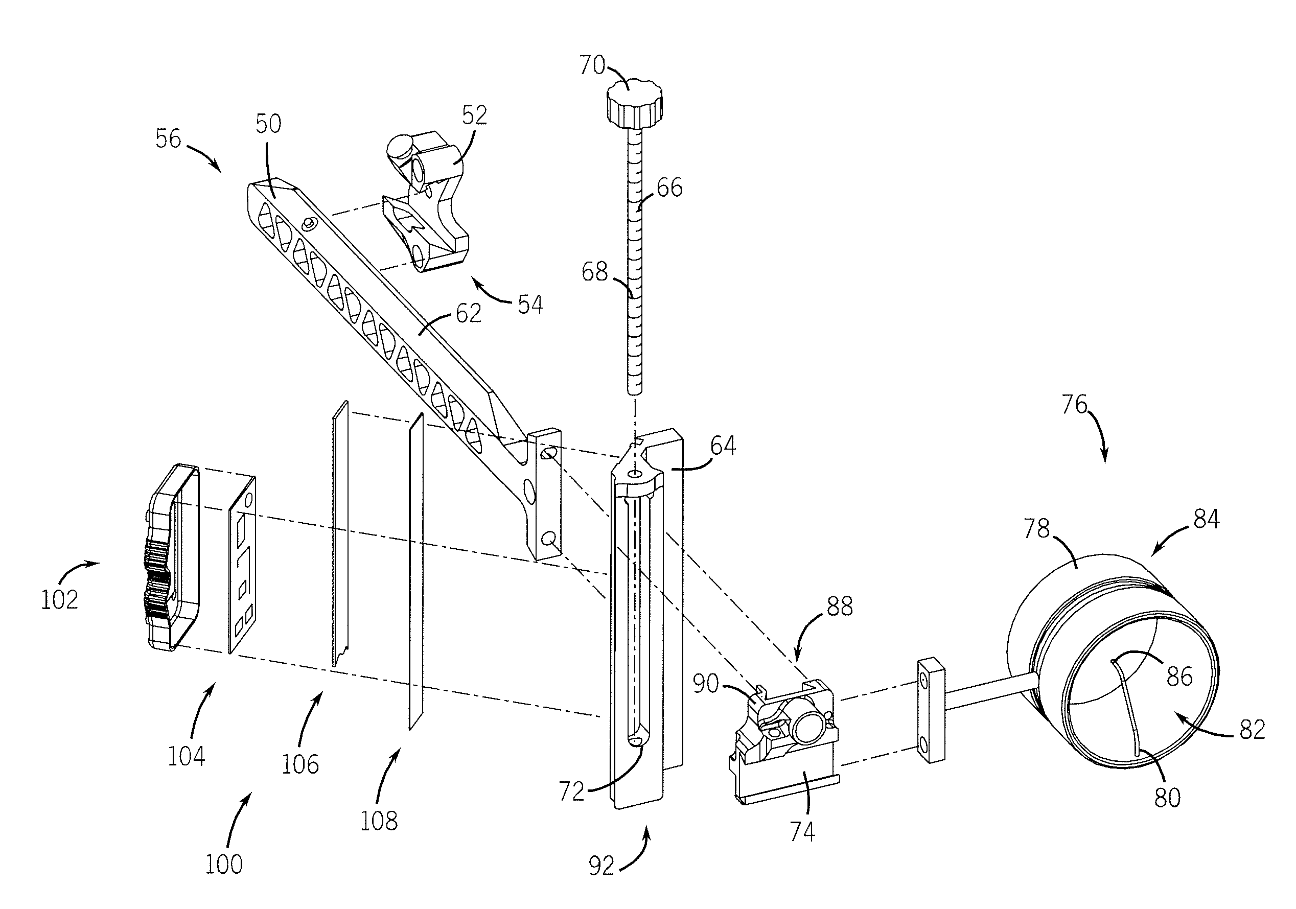
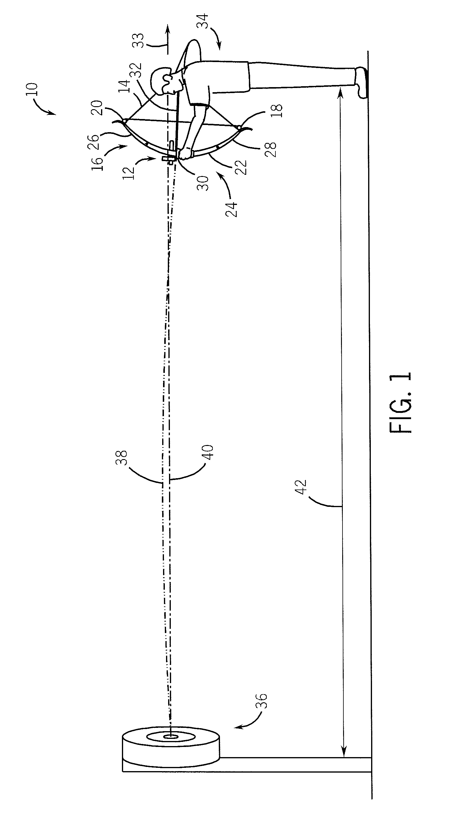
[0020]FIG. 1 shows a bow 10 equipped with a sight 12 according to the present invention. Bow 10 includes a drawstring 14 attached to a frame assembly 16 by a number of pulleys or cams 18, 20. Frame assembly 16 includes a riser 22 having a grip portion 24 and an upper limb 26 and a lower limb 28 attached thereto. As commonly understood such a construction forms an exemplary compound bow although the present invention is applicable with a number of the bow constructions such as recurve or longbows. A rest 30 is attached to riser 22 and is constructed to support an arrow 32 thereon. As an archer 34 pulls drawstring 14, arrow 32 translates rearward, indicated by arrow 33, relative to riser 22. Nocking a butt of arrow 32 in drawstring 14 ensures that arrow 32 is propelled, fired, or shot toward a target 36 when archer 34 releases a drawstring 14. Arrow 32 follows a projectile trajectory path 38 whereas the aim of archer 34 follows a substantially more linear path or a sight path 40. Sigh...


PUM


Abstract

A bow sight that includes a body, a stator, a slide, and an electronic sight position indicator. The body is constructed to secure the sight to a bow and the stator and slide are attached to the body such as to allow relative motion between the stator and the slide. The position indicator is attached to the bow sight and electronically determines the relative position of the stator and the slide and thereby provides an indication of an orientation of an eyepiece relative to the bow.

Description

FIELD OF THE INVENTION[0001]The present invention relates to bows, and more specifically to a bow sight constructed to electronically assess and / or indicate the position of the sight relative to the bow.BACKGROUND OF THE INVENTION[0002]Archery bow sights generally include one or more movable pins that are secured to a support structure. The support structure is constructed to be attached to a bow. The sight is mounted to a bow so that when the bow string is drawn, the archer can look through the sight and align a pin or tip of a sight pin with a target. Regardless of the number of sight pins, for an archer to accurately utilize the sight, the sight must first be “sighted-in” or have the position of the pins associated with the trajectory of an arrow for given shooting conditions. Commonly, sighting-in a bow requires that an archer sequentially fire a number of arrows under normal conditions and yardages while incrementally adjusting the orientation of the sight pin relative to the b...

Claims


Application Information

Patent Timeline
IPC IPC(8): F41G1/467
CPCF41G1/467
Inventor KROENING, JR., JOHN W.
Owner SUPERIOR DESIGN
Why Eureka
Try Eureka