Fluid warming apparatus

a technology of flue gas heating and heating apparatus, which is applied in the direction of electric heating, therapeutic heating, therapeutic cooling, etc., can solve the problems of significant error in the measurement of the temperature of the heated air flow close to the heater, unintentional increase of the temperature of the air provided to the patient, and insufficient temperature representation of the measured temperature. to achieve the effect of maintaining the accuracy of any calibration weighting

Active Publication Date: 2021-10-19
THE SURGICAL INT
View PDF8 Cites 0 Cited by
  • Summary
  • Abstract
  • Description
  • Claims
  • Application Information

AI Technical Summary

Benefits of technology

[0009]Typically the fluid warming apparatus is configured in use to provide an input fluid flow to a temperature regulation tool (e.g. a forced air warming tool such as a forced air warming blanket) which uses the input fluid flow to adjust or maintain a temperature of a subject (such as a human patient). The input fluid flow to the temperature regulation tool typically comprises fluid from the heated fluid flow which has mixed. Therefore the input fluid flow to the temperature regulation tool typically has a more homogeneous temperature distribution in the distribution direction than the heated fluid flow. Due to the inhomogeneous temperature distribution of the said heated fluid flow in the said distribution direction, the temperature measurements of the individual temperature sensors are not necessarily indicative of the heated fluid flow as a whole or indeed of the temperature of the said input fluid flow. By providing at least two temperature sensors configured to measure temperatures of respective portions of the heated fluid flow having different temperatures, temperature measurement data more indicative of the temperature of the heated fluid flow as a whole can be obtained. This allows the temperature of the input fluid flow received by the temperature regulation tool to be more accurately predicted and / or regulated. In addition, the temperature sensors can be provided closer to the heater because it is not necessary for the said heated fluid flow to have physically mixed to obtain a more homogeneous temperature distribution before temperature can be accurately determined. This results in a faster (and reliable) detection of a temperature change in the heated fluid flow generated by the fan and the heater compared to existing fluid warming apparatuses which require the heated fluid flow to mix before a reliable temperature reading can be obtained.
[0024]It will be understood that the controller can react (e.g. by adjusting the heat output by the heater) more quickly (and accurately) to changes in temperature of the (first) heated fluid flow caused by changes in circumstances (e.g. the controller can better prevent the heater from overheating the (first) heated fluid flow, for example, in the event of a sudden blockade of the output fluid flow from the fluid warming apparatus) because of the faster (and reliable) detection of the temperature change.
[0052]Typically the temperature sensors (typically excluding the said further temperature sensor configured to measure the temperature of the fluid intake, where provided) are mechanically coupled to each other, typically by a mechanical coupling extending between them (such as a frame or a plate). This helps to fix the positions of the temperature sensors relative to each other and relative to the heater. This helps to maintain the accuracy of any calibration weightings applied to the temperature measurements provided by the temperature sensors by the controller.
[0078]It may be that the method comprises adjusting the said predetermined weightings, e.g. so as to optimise the accuracy and / or reproducibility and / or stability of a predicted temperature value or of the regulation of the temperature of the second heated fluid flow.

Problems solved by technology

Measuring the temperature of the heated air flow close to the heater is subject to significant error as it is unclear whether the temperature sensor is provided in a portion of the air flow which has been heated or in a portion which has been relatively unheated.
In addition, regardless of which portion of the air flow is measured, the measured temperature is not necessarily representative of the temperature of the air which will be incident on the patient (because the hot and cool portions of the air flow have not yet mixed).
If the heater remains on, the air trapped between the heater and the blockade continues to be heated, which can unintentionally increase the temperature of the air provided to the patient.
However, in forced air warmers in which temperature is measured far downstream of the heater and the fan (where the temperature distribution of the heated air flow is more homogeneous), it is not possible to quickly detect changes in temperature because of the time it takes for a change in temperature of the heated air flow generated by the fan and the heater to affect the downstream portion of the airflow where temperature is measured.
However, because some of the heat generated by the heater heats up components provided between the heater and the temperature sensors (e.g. the fan), the temperature sensors cannot quickly detect changes in the temperature of heated air flow generated by the fan and the heater, and thermal efficiency is low.

Method used


Image

  • Fluid warming apparatus
  • Fluid warming apparatus
  • Fluid warming apparatus

Examples


Embodiment Construction

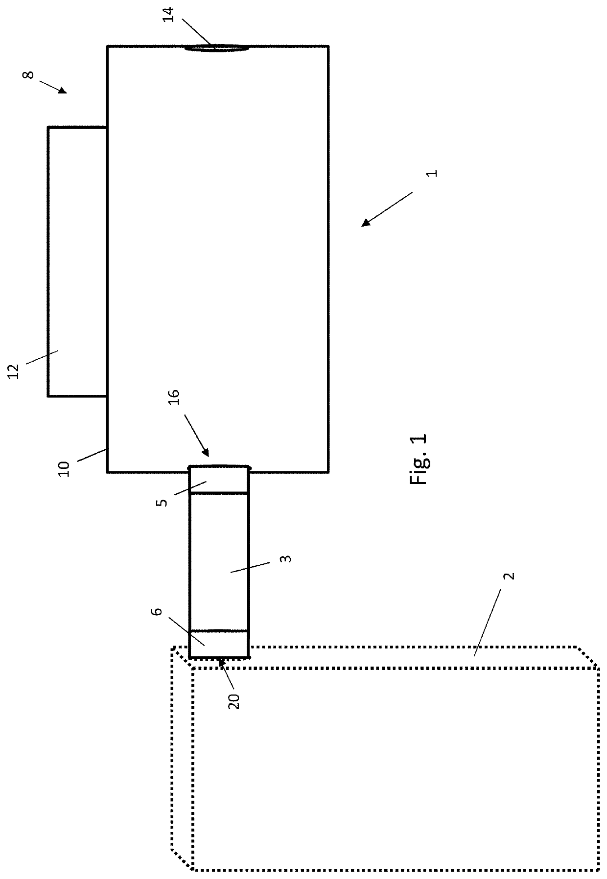
[0089]FIG. 1 is a block diagram showing a forced air warmer 1 fluidly coupled to a perforated blanket 2 by a flexible hose 3, the perforated blanket 2 being draped over a (typically human) patient (not shown) during a medical procedure or operation (typically when the patient is under a general anaesthetic). Air heated by the forced air warmer 1 is delivered to the blanket 2 through the hose 3. The blanket 2 contains a plurality of perforations (not shown) through which heated air received from the forced air warmer 1 is delivered to the patient to heat the patient by forced convection, thereby preventing the onset of unintentional hypothermia in the patient.

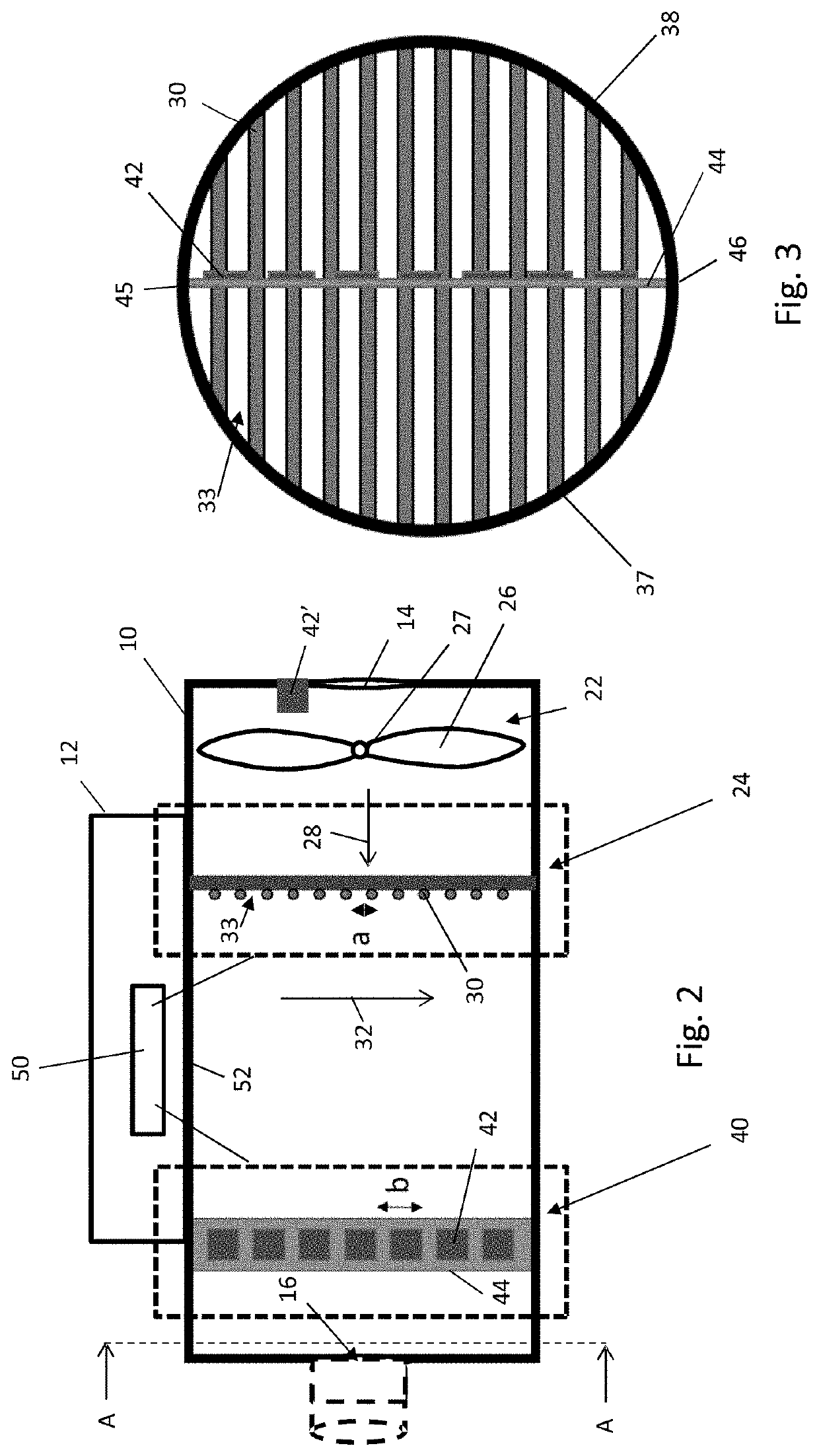
[0090]As shown in both FIGS. 1 and 2, the forced air warmer 1 comprises a housing 8 having a first hollow, cylindrical portion 10 (although it will be understood that the first housing portion 10 is not necessarily cylindrical) and a second portion 12 coupled to (or integrally formed with) the first portion 10, the first portion...


PUM


Abstract

The invention provides fluid warming apparatus comprising: a fan; a heater, the fan and the heater being configured to generate a heated fluid flow having a principle flow direction and an inhomogeneous temperature distribution in a distribution direction perpendicular to the said principle flow direction; and a plurality of temperature sensors offset from each other in the said distribution direction, wherein at least two of the temperature sensors are configured to measure temperatures of respective portions of the heated fluid flow having different temperatures.

Description

[0001]This application claims priority to EP 16178448.3 filed Jul. 7, 2016, the entire contents of which are hereby incorporated by reference.FIELD OF THE INVENTION[0002]The invention relates to: fluid warming apparatus; a patient temperature regulation system comprising a fluid warming apparatus; and a method of warming fluid.BACKGROUND TO THE INVENTION[0003]Devices used for forced air warming typically consist of a fan and a heater to generate a flow of heated air and a temperature regulation mechanism for controlling the temperature of the heater and thus of the heated air flow. The heater is typically provided downstream of the fan to maximise thermal efficiency. The heated air flow is applied to a patient via a hose and a perforated blanket which is draped over a patient's body. Openings in the blanket cause the heated air to exit the blanket onto the patient, thereby heating the patient by forced convection. To ensure that the air which is supplied to the patient is at the cor...

Claims


Application Information

Patent Timeline
Patent Type & Authority Patents(United States)
IPC IPC(8): A61F7/00A61F7/02A61F7/08H05B1/02A61B90/17
CPCA61F7/0097A61B90/17A61F7/0085A61F7/02A61F7/08H05B1/02H05B1/0272H05B1/0297A61F2007/006A61F2007/0055A61F2007/0072A61F2007/0086A61F2007/0093A61F2007/0095A61F2007/0096A61F2007/0233
Inventor TIJSSEN, PETERVAN OUDENALLEN, ROBERTUS GERARDUSKEUNING, JASPERVAN DEN BERG, BERT
Owner THE SURGICAL INT
Why Eureka
Try Eureka