Sensorless control method and apparatus for a motor drive system

a sensorless control and motor drive technology, applied in the direction of motor/generator/converter stopper, dynamo-electric converter control, instruments, etc., can solve the problems of reducing system reliability, increasing system complexity, and affecting the performance of the control system, and achieve the effect of fast calculations

Inactive Publication Date: 2005-01-13
HONEYWELL INT INC
View PDF19 Cites 135 Cited by
  • Summary
  • Abstract
  • Description
  • Claims
  • Application Information

AI Technical Summary

Benefits of technology

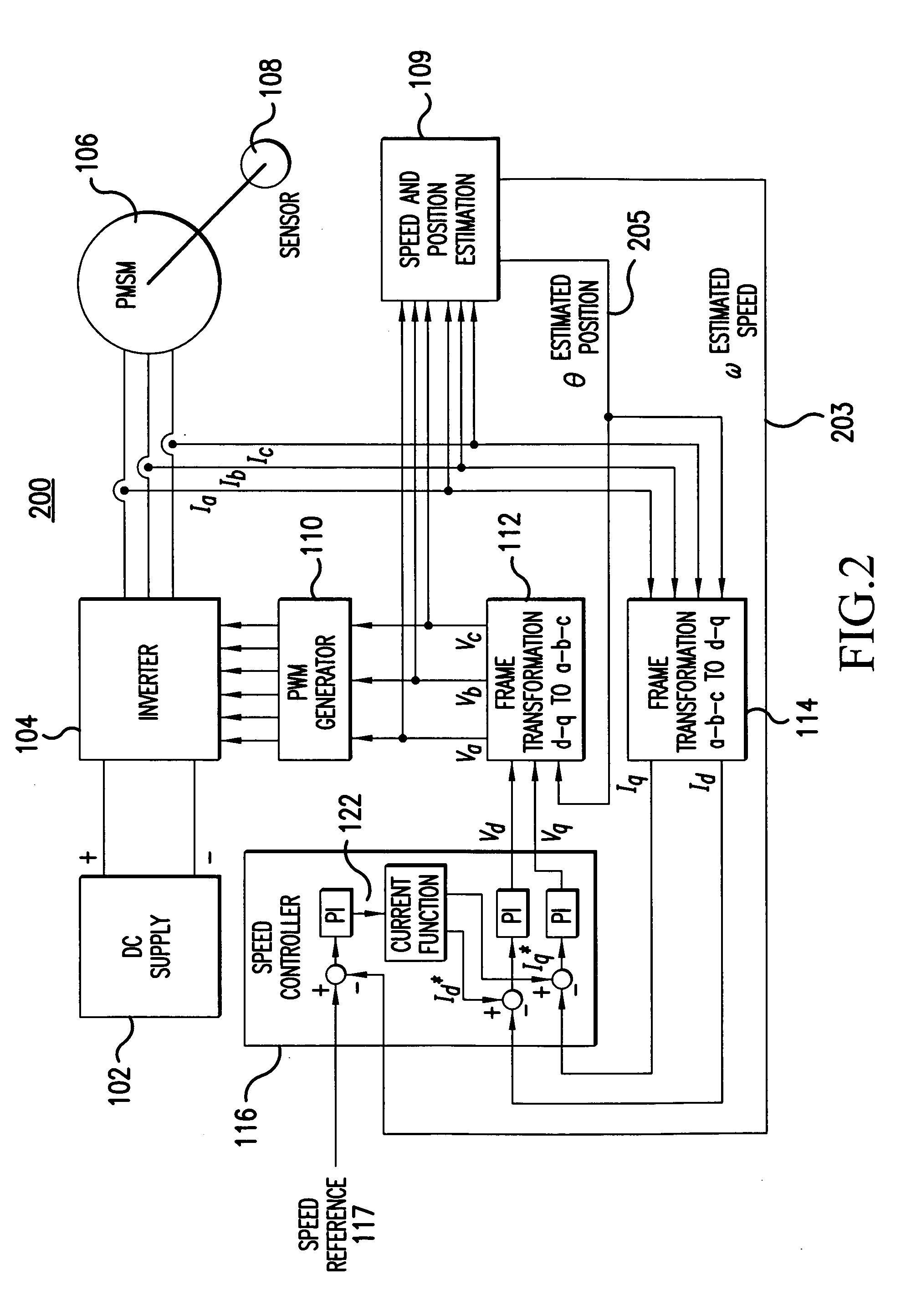
The system of the present invention overcomes the previously mentioned problems by providing a predictive, state observer control system for a motor that uses an Extended Kalman Filter (EKF) to first estimate the initial rotor position, and then accurately predict rotor position and / or speed in quasi real-time for a variety of dynamic load conditions during operation without using a speed / position sensor. The EKF-based model described herein for an entire integrated motor-drive system includes power electronics and associated digital controls circuitry for the system and performs fast calculations for ease of digital signal processing and controls implementation. The overall motor-drive control system model includes an EKF (extended Kalman filter) estimator, speed controller, a current controller, a DC-AC power conversion inverter module, a Pulse Width Modulated (PWM) gating pattern generator, and a variable speed / torque load component. During operation, EKF estimator module estimates rotor speed, rotor position, and current states based on reference voltages and currents generated by speed and current controllers input from frame transformers. Also, the obtained, accurate sensorless position estimations are used to achieve frame-transformed reference currents and reference voltages which are used as feedback signals in the system and as drive signals to control power to be applied to a PMSM load.

Problems solved by technology

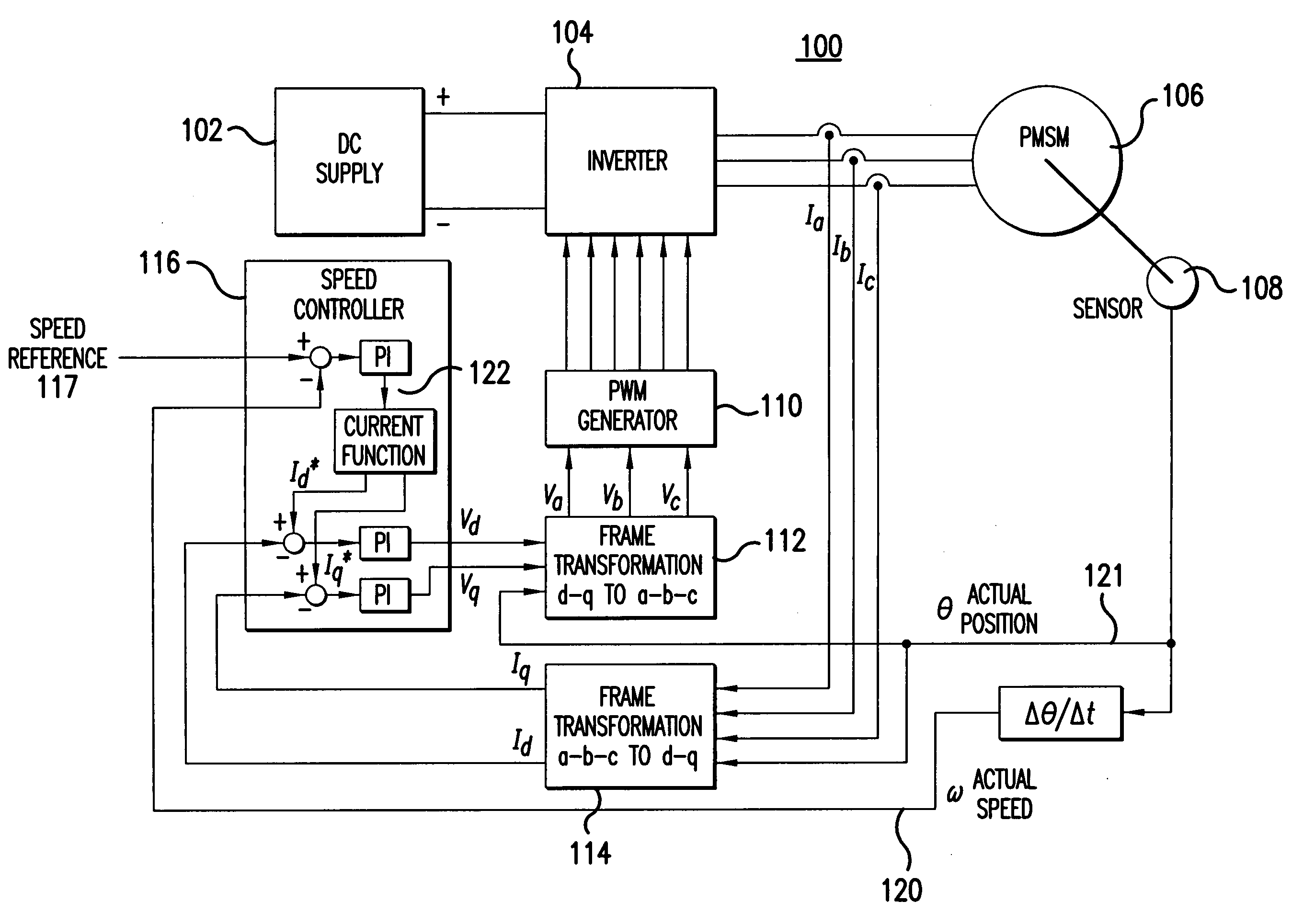
This technique shown in FIG. 1, however, increases system complexity and decreases system reliability.
Advantageously, this process may be used for both brushless DC motors (BLDCM) and PMSMs, but control system performance may degrade based on the quality and accuracy of flux-linkage estimates and measurements of system voltages and currents.
Additionally, control system accuracy may degrade from system harmonics and noise, machine parameter variations due to temperature changes and magnetic saturation.
Other prior art sensorless methods utilize a state observer technique but these methods are susceptible to motor drive system parameter variation and require complex non-linear control theory, which make these other methods difficult to fine-tune and implement.
Such methods also suffer from additional limitations including lack of any accurate information on the initial rotor position which is further complicated by initial speed / position convergence problems, and the need for injecting a current pulse at the start-up of the motor to avoid a stall condition.
Lack of proper operation of such methods has prevented their accuracy and effectiveness over the full speed and torque range, required by dynamic loads, which is a main reason for sensorless control of drive systems not becoming wide-spread.

Method used


Image

  • Sensorless control method and apparatus for a motor drive system
  • Sensorless control method and apparatus for a motor drive system
  • Sensorless control method and apparatus for a motor drive system

Examples


Embodiment Construction

Embodiments of the present invention are more specifically set forth in the following description, with reference to the appended drawings. In the following description and accompanying drawings like elements are denoted with similar reference numbers. Further, well-known elements and related explanations are omitted so as not to obscure the inventive concepts presented herein.

U.S. patent application Ser. No. 10 / 244,496 (“the '496 application”), filed Sep. 16, 2002 and titled “Position Sensor Emulator for a Synchronous Motor / Generator,” which discloses embodiments for deriving rotor position information from phase voltage signals output by main generator stator windings (stator phase windings) of a synchronous motor generator, is incorporated herein by reference.

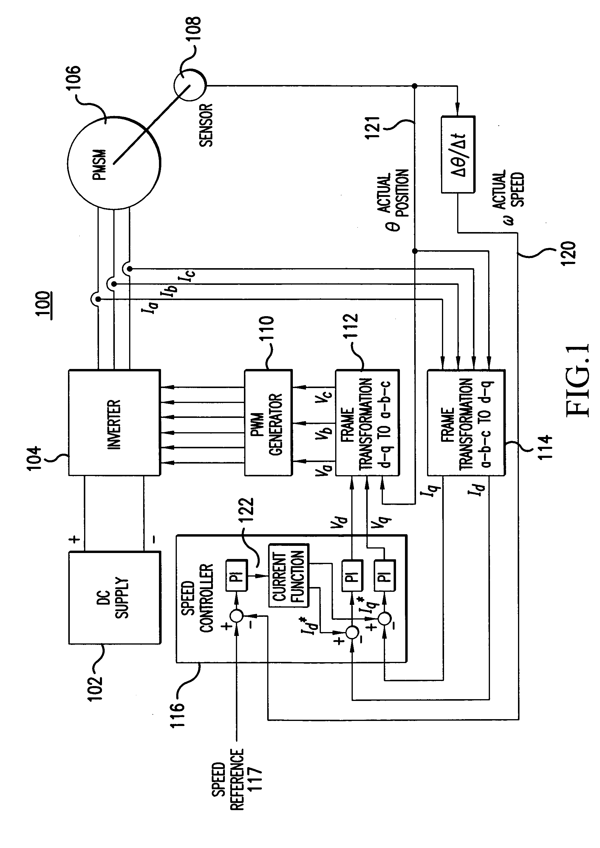
The motor drive systems 100, 200 of FIGS. 1, 2 previously described along with the motor drive system of 1200 shown in FIG. 12 illustrate motor generator systems to which principles of the present invention may be appli...


PUM


Abstract

A method and apparatus provide a state observer control system 600 for a motor 106 that uses an extended Kalman filter 330 to predict initial rotor position and afterwards accurately predict rotor position and / or speed under variable types of loading conditions. A control system model 300 is generated that allows variable setting of an initial rotor position to generate estimated rotor position and speed as outputs. The control system model 300 includes an EKF (extended Kalman filter) estimator 330, speed controller 322, a current controller 324, and a variable load component 310. During operation, EKF estimator 330 estimates rotor speed 327 and position 333 based on reference voltages 402, 404 and currents 1325 generated by speed and current controllers 322, 324 and input from frame transformers 326, 328. Additionally, the reference currents and voltages 402, 404, 1325 are frame-transformed to be used as feedback signals 418, 346 in the system 600 and as drive signals to control power to be applied to a motor load 602.

Description

FIELD OF THE INVENTION The present invention relates to predictive control systems for various loads, and more particularly to a robust, sensorless predictive method and apparatus for accurately detecting rotor speed and position in a synchronous motor generator system. BACKGROUND OF THE INVENTION An important component of a controlled motor-drive system is an electromechanical machine. Depending on the application, such machines can be used either as a generator or a motor through the interaction of their “stator magnetic field” and their “rotor magnetic field”, to convert mechanical energy to electrical energy, or vice versa, as is well known in the field of controlled motor-drive systems. Generally at least four distinct types of machines can be identified, based on how the stator and rotor magnetic fields are produced and interacted with each other. These types include a Permanent Magnet Synchronous Machine (PMSM), wherein a rotating magnetic field is generated by the applicat...

Claims


Application Information

Patent Timeline
Patent Type & Authority Applications(United States)
IPC IPC(8): G05B13/04H02P21/13
CPCH02P21/13G05B13/048
Inventor QIU, MINGKOJORI, HASSAN A.WU, BIN
Owner HONEYWELL INT INC
Why Eureka
Try Eureka