

Compression Molding Apparatus
- Summary
- Abstract
- Description
- Claims
- Application Information
AI Technical Summary
Benefits of technology
Problems solved by technology
Method used
Image

Examples
Embodiment Construction
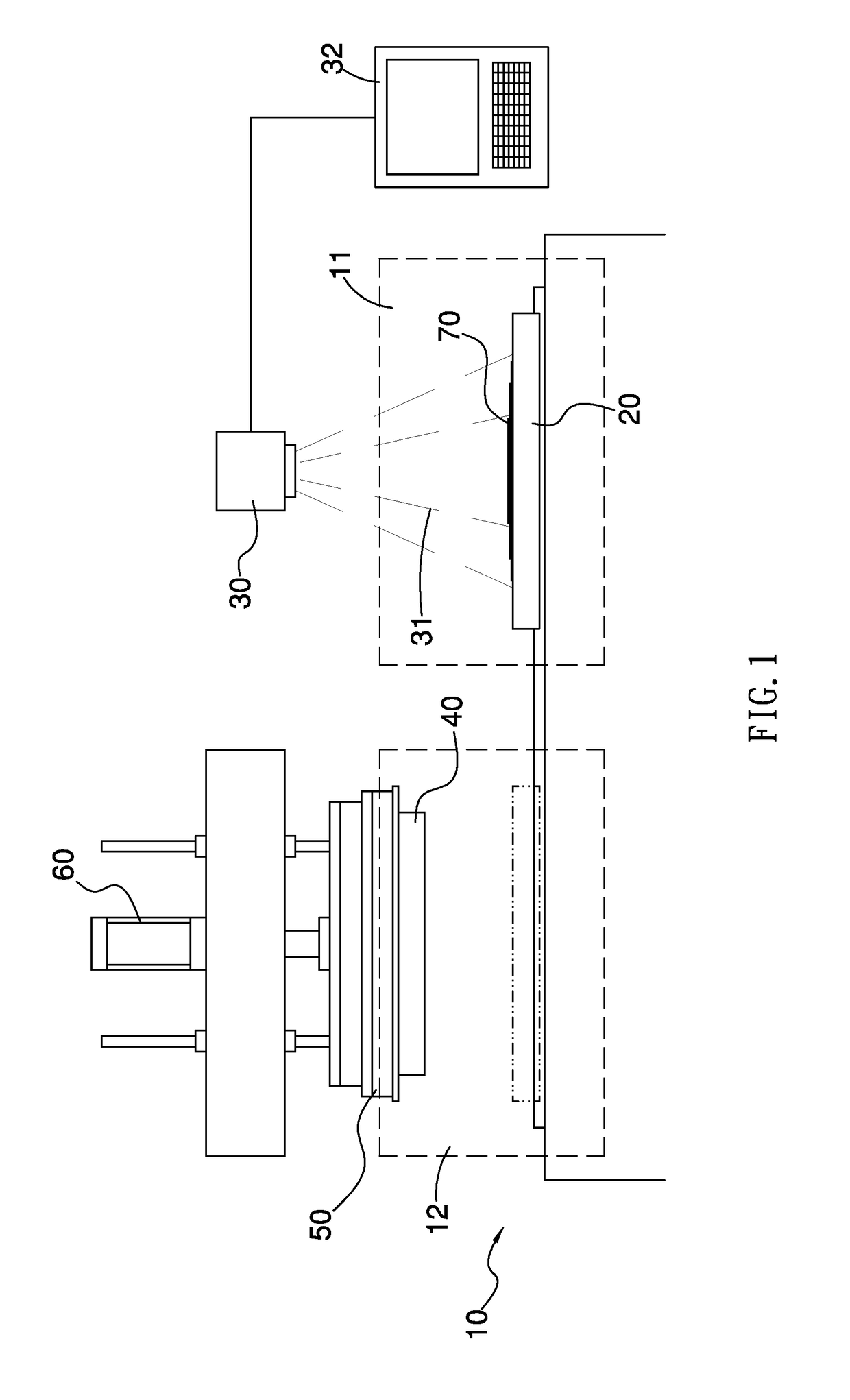
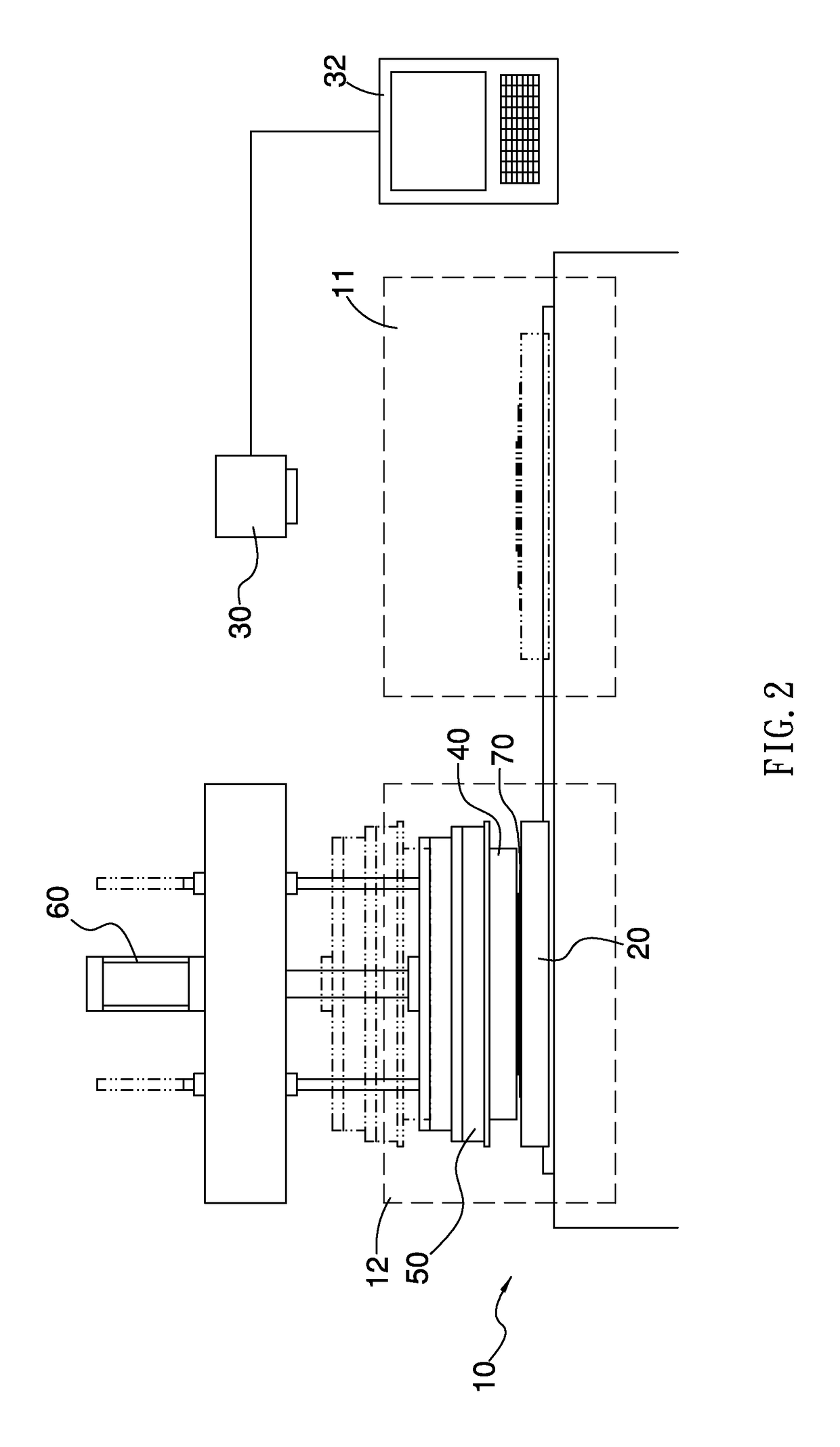
[0024]With reference to FIGS. 1 to 2, a compression molding apparatus according to a first embodiment of the present invention comprises: a base 10, a carrying platform 20, a projector 30, a pressing mold 40, a heater 50, and a lifting mechanism 60.
[0025]The base 10 includes a material feeding zone 11 and a molding zone 12.
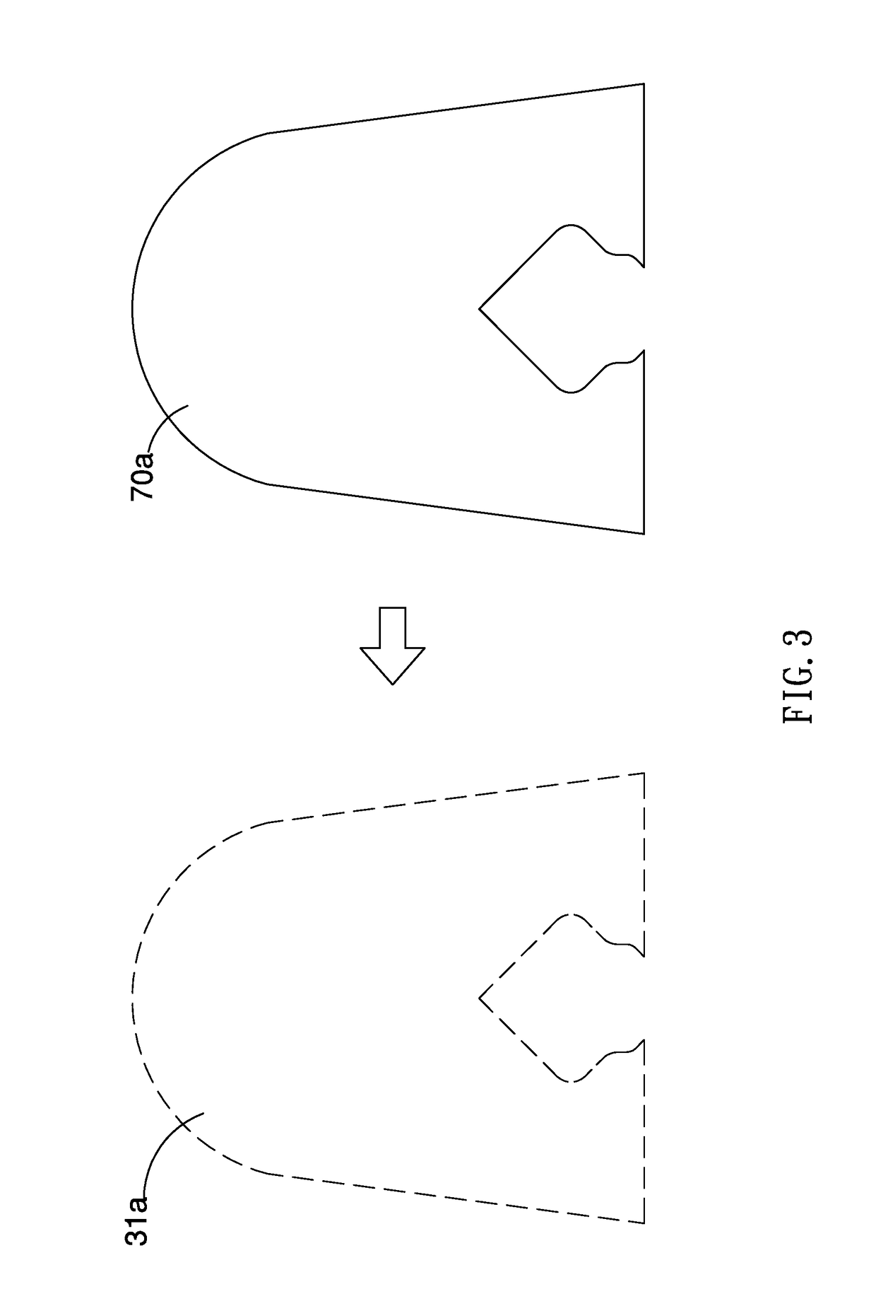
[0026]The carrying platform 20 moves into the molding zone 12 from the material feeding zone 11, and when the carrying platform 20 is located in the material feeding zone 11, plural connecting pieces 70 of different shapes are stacked on the carrying platform 20 in turn. In this embodiment, each connecting piece 70 is any one of thermoplastic material, cloth, leather, and a combination of the thermoplastic material, the cloth, and the leather. The carrying platform 20 includes three-dimensional patterns formed thereon, and the thermoplastic material has a temperature resistant layer formed on a first surface thereof and has a low temperature layer formed on a seco...
PUM
 Abstract
Description
Claims
Application Information