Method and apparatus for monitoring a region

a technology for monitoring and regions, applied in mechanical apparatus, instruments, television systems, etc., can solve problems such as no way compromising accuracy, and achieve the effect of fast and reliable evaluation

Inactive Publication Date: 2008-12-25
SICK AG
View PDF7 Cites 9 Cited by
  • Summary
  • Abstract
  • Description
  • Claims
  • Application Information

AI Technical Summary

Benefits of technology

[0008]It is therefore an object of the in...

Problems solved by technology

However, this in no...

Method used


Image

  • Method and apparatus for monitoring a region
  • Method and apparatus for monitoring a region
  • Method and apparatus for monitoring a region

Examples


Embodiment Construction

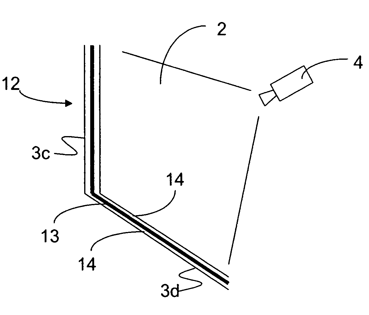
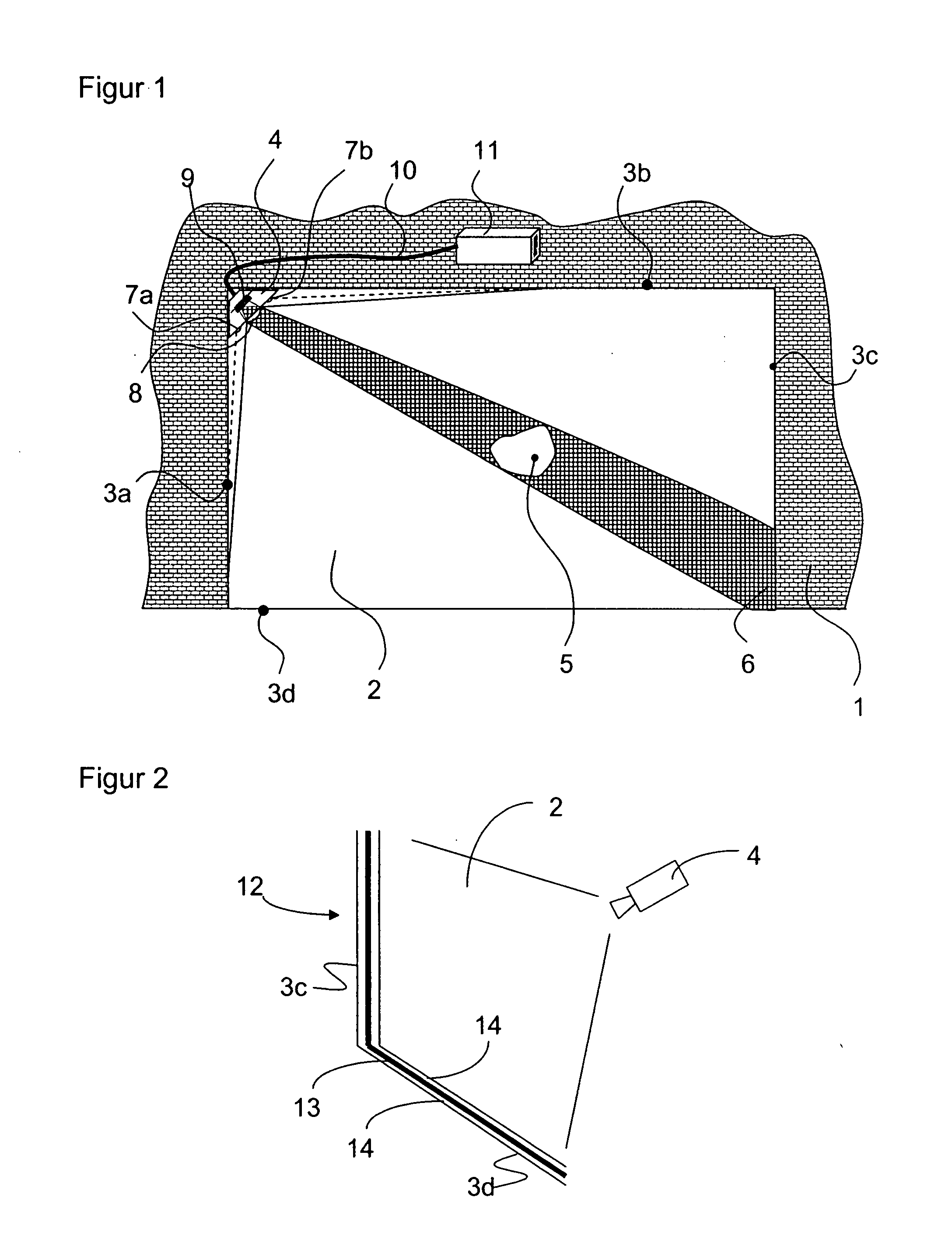
[0035]FIG. 1 is a schematic overview of one embodiment of the invention. A partition 1 has an aperture 2 which is defined by marginal areas 3a-3d. A camera 4 in one corner of aperture 2 takes a picture of the two opposite marginal areas 3c, 3d. In the drawing the camera 4 has an aperture angle greater than 90° and therefore also captures portions of marginal areas 3a, 3b. In order to monitor the entire passage aperture 2, the marginal areas 3c, 3d suffice as the monitored area. However, depending on the application, a subsection may also suffice.

[0036]The camera 4 monitors whether an object 5 is located in the passage aperture 2. Such an object 5 changes the image captured by the camera. Without the presence of an object 5 the camera image would show an undisturbed shaded area 6 of the monitored zone.

[0037]Two illumination systems 7a, 7b are arranged next to the camera 4. Two or more illumination systems 7a, 7b can also be symmetrically arranged relative to camera 4. However, one il...


PUM


Abstract

A method and device for monitoring a monitored area with at least one camera (4) and in which the monitored area has a contrast strip (12) with at least one bright partial strip (13) and/or at least one dark partial strip (14) that extend in the longitudinal direction. A control unit (11) recognizes the obscuration of a minimum area of the bright partial strip (13) and/or the dark partial strip (14) as the entry of an object (5) into the monitored area. The control unit (11) detects from an image of the camera (4) the obscuration in columns which are oriented transverse to the contrast strip (12). A violation of the signature of the contrast strip (12) is recognized when a first minimum number of bright pixels between the bright beginning (Y2) and the bright end (Y3) of the bright partial strip (13) and/or a second minimum number of dark pixels between the dark beginning (Y1) and the dark end (Y2) of the dark partial strip in the respective columns, and the obscuration of the minimum area as the obscuration of a predetermined number of side-by-side columns have been detected.

Description

RELATED APPLICATIONS[0001]This application claims the priority of European Patent Application No. 06024677.4 filed Nov. 29, 2006, the disclosure of which is incorporated herein by reference.BACKGROUND OF THE INVENTION[0002]The invention relates to a device and a method for monitoring a monitored area or region, as disclosed in the preambles of claim 1 and / or claim 11.[0003]Monitoring systems are used in a variety of applications in order to monitor in an automated manner changes in the monitored area. One such application is to protect a hazardous region where the entry of an object into the region is detected and classified according to pre-established rules that establish whether the detection of the object should trigger a warning signal or, for example, turn off a protected machine. This type of access control is predominantly implemented with light grids or laser scanners, but can also be achieved with a camera.[0004]A direct digital recognition of the object is expensive and c...

Claims


Application Information

Patent Timeline
IPC IPC(8): H04N7/18G06V10/145
CPCF16P3/14G06K9/2036G08B13/1961F16P3/142G06V10/145
Inventor BRAUNE, INGOLFROTHENBERGER, BERND
Owner SICK AG
Why Eureka
Try Eureka