Speckle reduction using a tunable liquid lens

a liquid lens and tunable technology, applied in the field of laser image projection systems, can solve the problem of speckle phenomenon, blockage of laser image projection, etc., and achieve the effect of reducing speckle, reducing speckle, and reducing the amount of speckl

a liquid lens and tunable technology, applied in the field of laser image projection systems, can solve the problem of speckle phenomenon, blockage of laser image projection, etc., and achieve the effect of reducing speckle, reducing speckle, and reducing the amount of speckl

US20090096999A1Active Publication Date: 2009-04-16ALCATEL-LUCENT USA INC

Image

  • Speckle reduction using a tunable liquid lens
  • Speckle reduction using a tunable liquid lens
  • Speckle reduction using a tunable liquid lens

Examples


Embodiment Construction

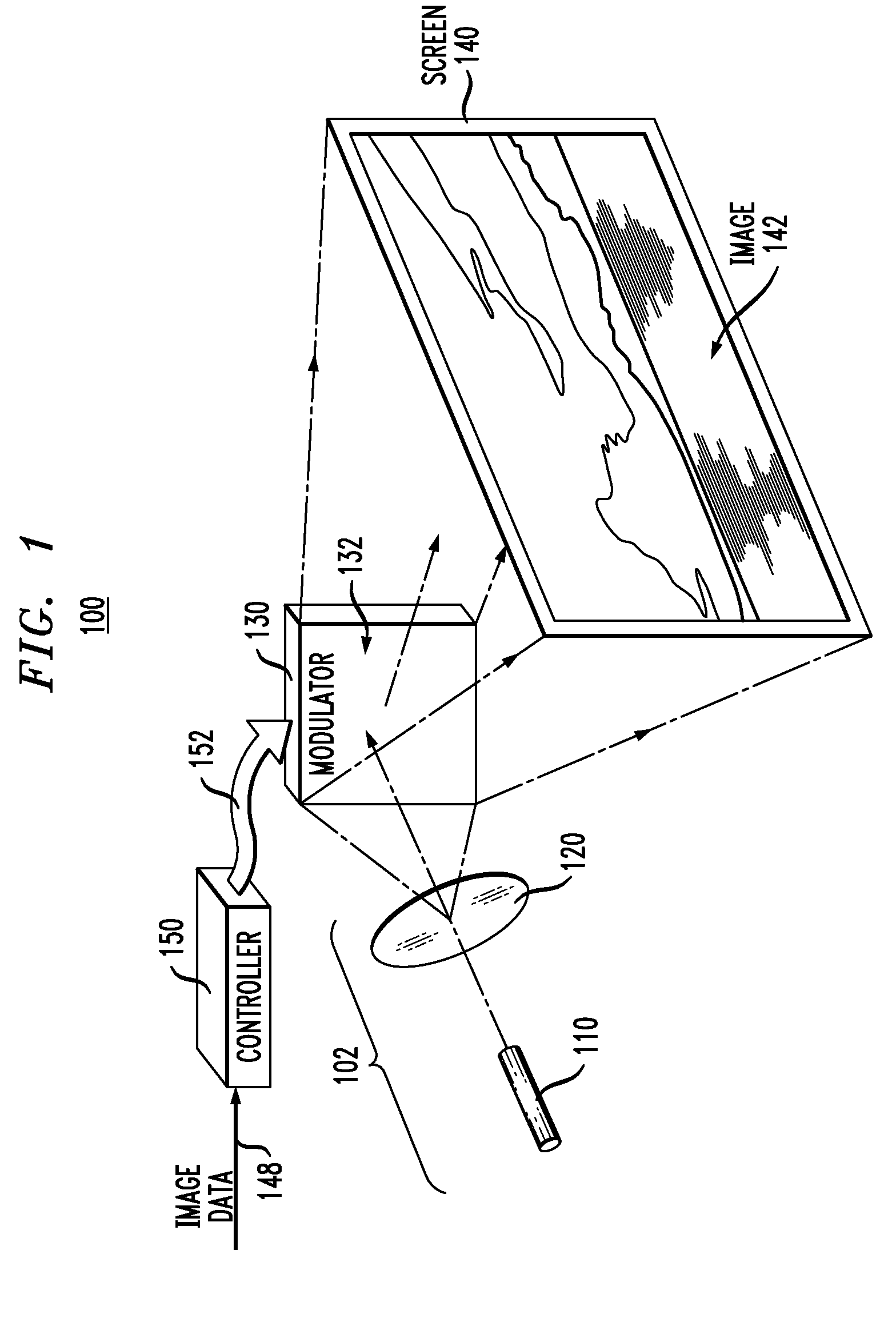
[0015]Herein, speckle reduction typically involves averaging two or more independent speckle configurations within the spatial and / or temporal resolution of the detector, such as the human eye. For the human eye, the averaging time is related to a physiological parameter called the flicker fusion threshold or flicker fusion rate. More specifically, light that is pulsating at a rate lower than the flicker fusion rate is perceived by humans as flickering. In contrast, light that is pulsating at a rate higher than the flicker fusion rate is perceived as being steady. Flicker fusion rates vary from person to person and also depend on the individual's level of fatigue, the brightness of the light source, and the area of the retina that is being used to observe the light source. Very few people perceive flicker at a rate higher than about 75 Hz. In cinema and television, frame delivery rates between 20 and 60 Hz, e.g., 30 Hz, are normally used. For the overwhelming majority of people, the...


PUM


Abstract

A representative embodiment of the invention provides a projection system having a laser source that incorporates a tunable liquid lens and a spatial light modulator adapted to modulate light generated by the laser source to project an image on a viewing screen. The tunable liquid lens is adapted to vary focal length, alignment or position with respect to an optical element that is external to the lens, ability to diffuse light, and / or polarization rotation angle.

Description

BACKGROUND OF THE INVENTION[0001]1. Field of the Invention[0002]The present invention relates to laser projection systems.[0003]2. Description of the Related Art[0004]The use of lasers in projection systems enables the creation of vibrant images with extensive color coverage that may be difficult to achieve with conventional (non-laser) light sources. However, one significant obstacle to laser image projection is the speckle phenomenon. Speckle arises when coherent light scattered from a rough surface, such as a screen, is detected by an intensity detector (e.g., a human eye) that has a finite aperture (e.g., a pupil). The finite aperture leads to quantization of the detected image into a mosaic of spots. If light scattered from a spot on the screen interferes destructively at the aperture, then that spot appears as a relatively dark spot in the perceived image. On the other hand, if light scattered from a spot interferes constructively at the aperture, then that spot appears as a r...

Claims


Application Information

Patent Timeline
16 Apr 2009
Publication
US20090096999A1
IPC
G03B21/14
CPC
B82Y20/00; G02B3/14; G02B26/005; G02B27/48; G02F1/01; G02F1/0136; H04N9/3161; G02F1/29
Inventors
FRAHM, ROBERT E.; LOPEZ, OMAR D.