Real time desktop image warping system

a desktop and image technology, applied in the field of image warping software algorithm, can solve the problems of increasing the size and weight of the display device, affecting the display effect,

Active Publication Date: 2009-04-23
U S OF A AS REPRESENTED BY THE SEC OF THE NAVY
View PDF8 Cites 13 Cited by
  • Summary
  • Abstract
  • Description
  • Claims
  • Application Information

AI Technical Summary

Benefits of technology

[0018]The novelty of the RTIW software is in the use of the Microsft Windows OS's rendering capabilities to perform image processing as the user interacts with the host computer. Having the RTIW software invoke Microsoft Windows OS's rendering capability allows the Real Time Desktop Image Warping system to create a relatively distortion free image scene that can be distributed across any number of display units and can adapt to display units that vary in size and type.

Problems solved by technology

The information now being displayed, however, is getting harder to comfortably see with the naked eye as the portable devices are configured with smaller displays.
However, the Stark invention induces distortion at the image breaks coincident with the edge of each display unit.
This approach increases the size and weight of the display device and is therefore undesirable for use with portable devices and is undesirable for large wall mounted configurations.
This solution is expensive and therefore undesirable to consumers and manufacturers.
This solution reduces the size of the image gap between screens but does not avoid it all together and is also difficult to manufacture.
Although Stark's display system attempts to create a seamless image across the joined display units, there are undesired optical distortions in the image at the image breaks.
Another drawback of the BAE solution is that once the intentionally distorted image was created it was only compatible with the multi-display unit configuration for which it was aligned.
The BAE solution is not performed in real time, is processing intensive, cannot process a video stream and is only useful for a fixed set of display units.

Method used


Image

  • Real time desktop image warping system
  • Real time desktop image warping system
  • Real time desktop image warping system

Examples


Embodiment Construction

[0030]It is to be understood that the foregoing general description and the following detailed description are exemplary and explanatory only and are not to be viewed as being restrictive of the present invention, as claimed. Further advantages of this invention will be apparent after a review of the following detailed description of the disclosed embodiments which are illustrated in the accompanying drawings and described in the appended claims.

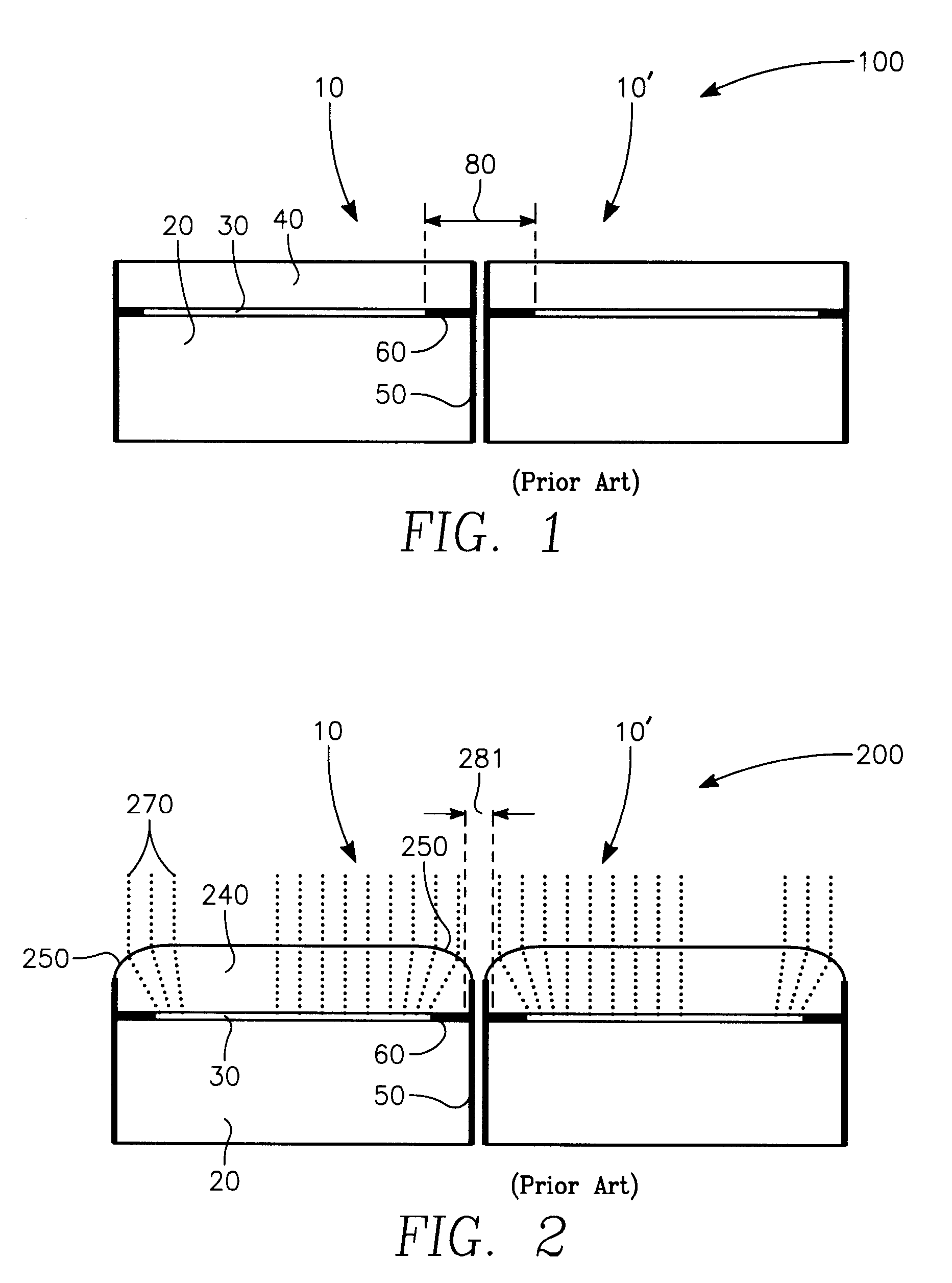
[0031]FIG. 1 depicts a sectional view through the edge of two identical and adjacent display screens 100. In the preferred embodiment the display screens 10 and 10′ are a Liquid Crystal Display (LCD) type. Applicant's invention is not limited to any particular type of display screen. The display screen 10 has a substrate 20, which can additionally include a glass plate, a polarizing element or a back light element. As depicted, the substrate 20 does not include a glass plate, a polarizing element or a back light element. Layered upon the sub...


PUM


Abstract

The present invention relates to an image warping software algorithm for a real time alteration of a display scene running under the Microsoft Windows Operating System. The image warping software algorithm alters the display scene and allows an observer to view the display scene as a single unbroken image when the display scene is distributed across multiple display screens. The purpose of the image warping software algorithm is to significantly reduce the distortion observed at the abutting edges of the joined display screens.

Description

STATEMENT REGARDING FEDERALLY SPONSORED RESEARCH OR DEVELOPMENT[0001]The invention described herein may be manufactured and used by or for the government of the United States of America for governmental purposes without the payment of any royalties thereon or therefore.STATEMENT TO INCORPORATE COMPUTER PROGRAM LISTINGS[0002]This application incorporates herein, by reference, the following twelve computer program listings as part of the originally filed specification:1. AboutCS.txt1KB in size.File creation date is 8 / 24 / 2006.2. About.DesignerCS.txt5 KB in size.File creation date is 8 / 24 / 2006.3. ConfigCS.txt24 KB in size.File creation date is 8 / 31 / 2006.4. ConfigDesignerCS.txt24 KB in size.File creation date is 8 / 24 / 2006.5. DetailsCS.txt5 KB in size.File creation date is 8 / 24 / 2006.6. DetailsDesignerCS.txt15 KB in size.File creation date is 8 / 24 / 2006.7. PlatFormInvokeGDI32CS.txt2 KB in size.File creation date is 5 / 24 / 2006.8. PlatFormInvokeUSER32CS.txt2 KB in size.File creation date is 5 / ...

Claims


Application Information

Patent Timeline
Patent Type & Authority Applications(United States)
IPC IPC(8): G09G5/00
CPCG06F3/1446G06T5/006G09G5/14G09G2340/12G09G2310/0232G09G2340/0407G09G2300/026
Inventor MILLER, STEPHEN
Owner U S OF A AS REPRESENTED BY THE SEC OF THE NAVY
Why Eureka
Try Eureka