Rapidly Deployable, Remotely Observable Video Monitoring System

Inactive Publication Date: 2009-04-23
MASTEN JR JAMES W
View PDF7 Cites 51 Cited by
  • Summary
  • Abstract
  • Description
  • Claims
  • Application Information

AI Technical Summary

Benefits of technology

[0010]This is a very different supporting construction from traditional video monitoring systems. As confidence grows in the automated detection technology, the force-multiplying effects will enable reactive personnel to cover very large areas. By this means, the system will dramatically enhance the value of the

Problems solved by technology

Social scientists may argue that as distances shrink and populations grow, conflict at many levels would be inevitable.
Another aspect of the problems of the fixed camera technology as currently used is the lack of sufficient coverage.
Cameras with sufficient resolution to enable some forms of automatic alert or threat identification would have very limited fields of view.
So

Method used


Image

  • Rapidly Deployable, Remotely Observable Video Monitoring System
  • Rapidly Deployable, Remotely Observable Video Monitoring System
  • Rapidly Deployable, Remotely Observable Video Monitoring System

Examples


Example

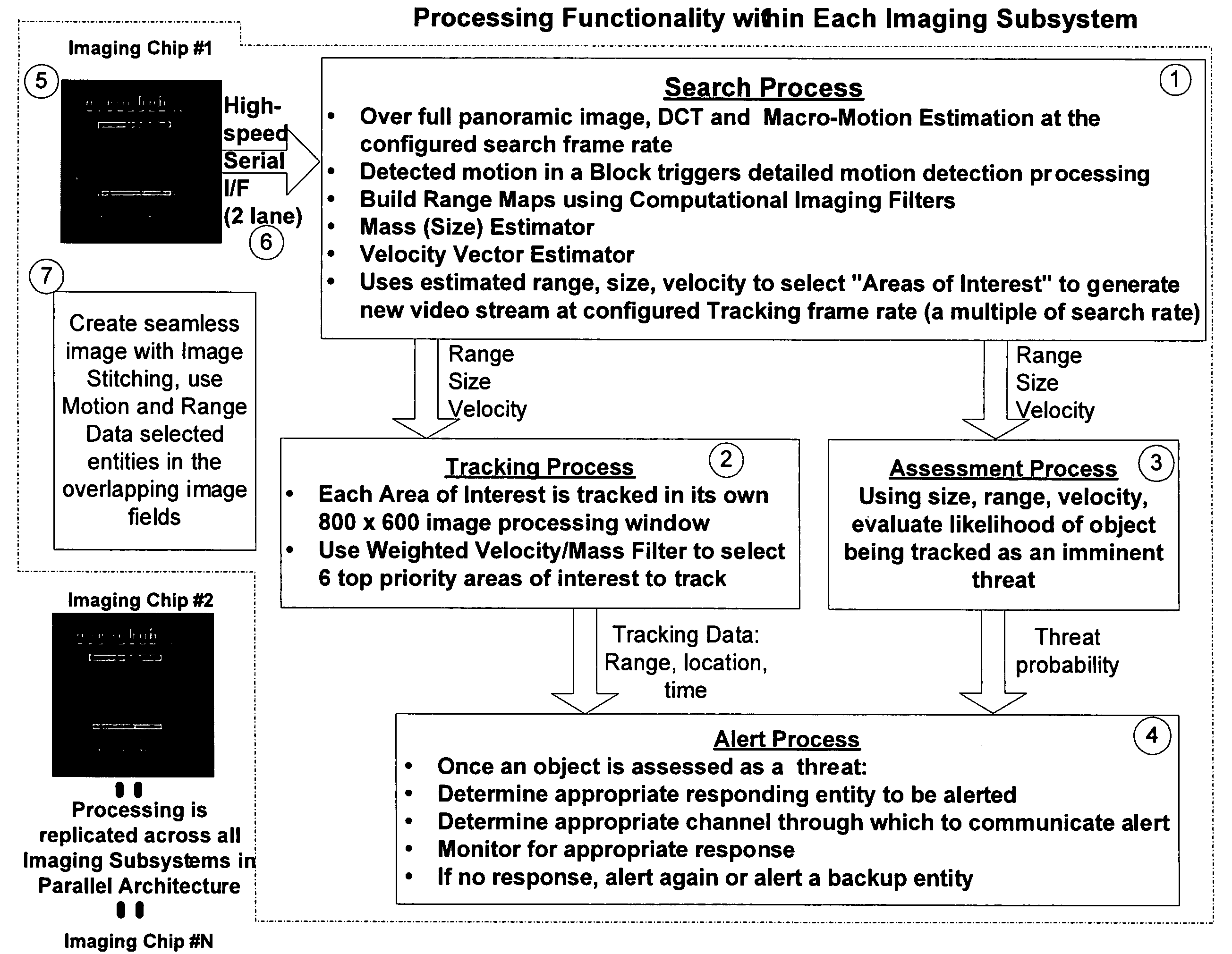
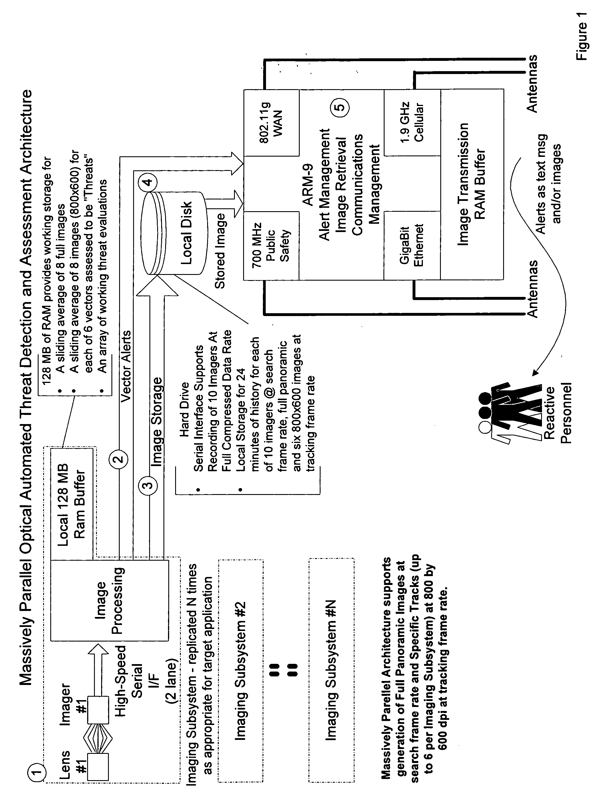
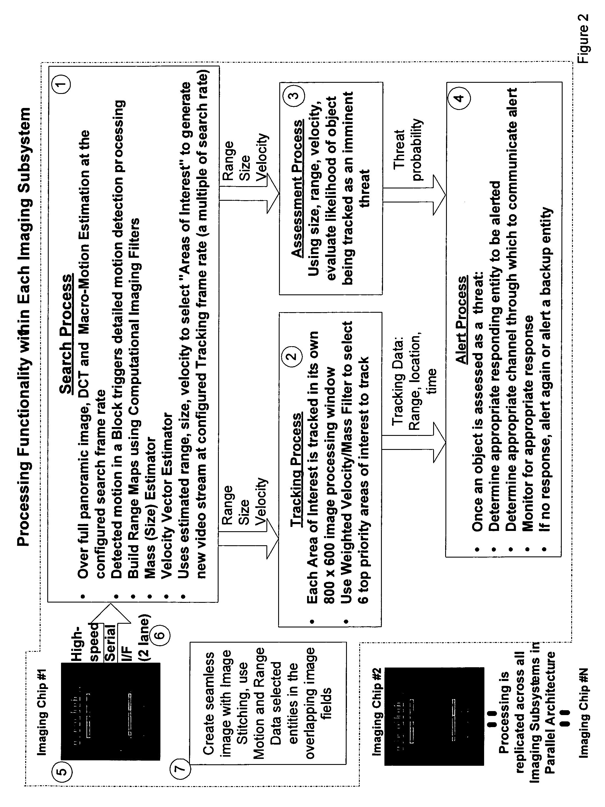
[0033]The central feature of this apparatus is the replicable architecture of the individual lens, imaging chip and the portion of the processing architecture assigned to each lens / imaging chip unit (herein referred to as the “Imaging Subsystem”), creating a highly parallel structure of sub-systems. The architecture supports a family of cameras, each designed using more or fewer of the Imaging Subsystems, chosen so that resolution and field of view sufficient to the target application are delivered by the apparatus. Sufficient resolution and field of view are defined as that which is required to enable fully automated threat detection and the delivery of alerts to a responsive resource with enough temporal margin to enable interdiction or corrective action.

[0034]Key to the utility of this invention is the low-cost reflective lens component of the Imaging Subsystem. Although the core catoptric lens has not changed since Isaac Newton, the implementation of the reflective lens in this ...


PUM


Abstract

A panoramic imaging threat detection and alert system to automate the detection, localization, tracking and assessment of moving objects within a specified field of view. This system utilizes an array of large-scale imaging chips, an array of reflective lenses coded for computational imaging, passive distance measurement and high-speed processors to determine the characteristics of objects of interest. This system selects moving objects to further evaluate for threat assessment and communicates object size, speed, distance and acceleration to a designated threat assessment center or personnel for further action.

Description

CROSS-REFERENCES TO RELATED APPLICATIONS[0001]This application claims priority to U.S. Provisional Application 60 / 939,319 filed on May 21, 2007, which itself claims priority to U.S. Provisional Application 60 / 917,049, filed on May 9, 2007. The foregoing applications are hereby incorporated by reference in their entirety as if fully set forth herein.STATEMENT REGARDING FEDERALLY SPONSORED RESEARCH OR DEVELOPMENT[0002]Not ApplicableINCORPORATION-BY-REFERENCE OF MATERIAL SUBMITTED ON A COMPACT DISC[0003]Not ApplicableBACKGROUND OF THE INVENTION[0004]The world situation requires constant vigilance against a variety of threats. Social scientists may argue that as distances shrink and populations grow, conflict at many levels would be inevitable. Whatever the cause or the reason, most of a nation's assets now require monitoring as a protection against some kind of threat by internal, external, foreign or domestic human forces. The results are a current need to monitor borders, pipelines, ...

Claims


Application Information

Patent Timeline
IPC IPC(8): H04N7/18
CPCG08B13/19608G08B13/19613H04N5/2254H04N7/18H04N5/2259H04N5/232H04N5/23238H04N5/2258H04N23/45H04N23/58H04N23/698H04N23/695
Inventor MASTEN, JR., JAMES W.
Owner MASTEN JR JAMES W
Why Eureka
Try Eureka