Three-dimensional image formation device

Inactive Publication Date: 2011-01-06
TENDRIL TECH
View PDF7 Cites 36 Cited by
  • Summary
  • Abstract
  • Description
  • Claims
  • Application Information

AI Technical Summary

Benefits of technology

[0008]It is a primary objective of the present invention to overcome the shortcomings of the prior art by providing a 3D image formation device comprising a mounting box, an image source device, a plurality of transparent reflecting lenses and a top panel, wherein reflection principles are used for reflecting a plurality of image s

Problems solved by technology

Positions of left and right eyes are different, so that there is a slight difference between the images observed by the left and right eyes, and such difference becomes a main cause of producing 3D images.
Although the pr

Method used


Image

  • Three-dimensional image formation device
  • Three-dimensional image formation device
  • Three-dimensional image formation device

Examples


Example

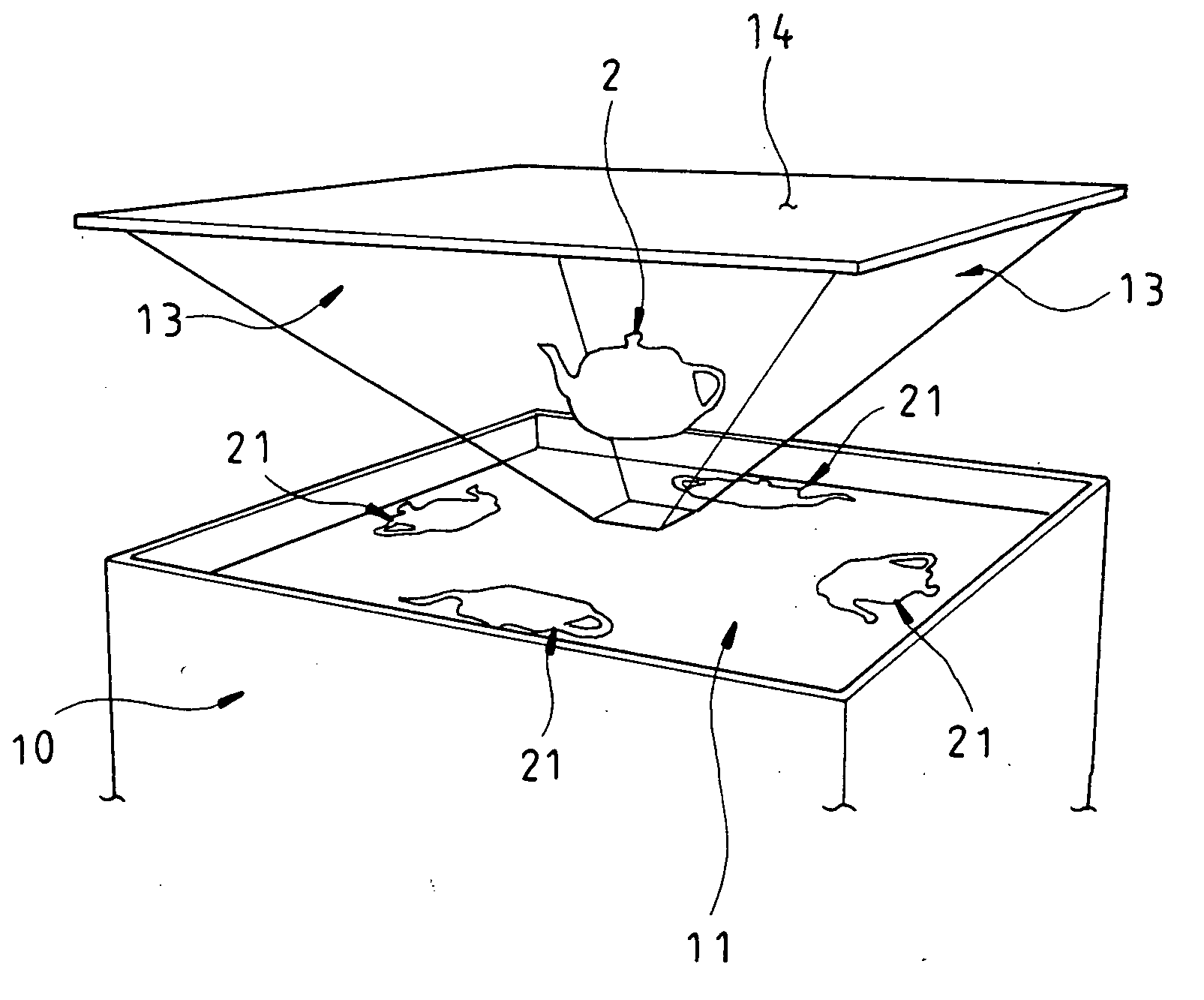
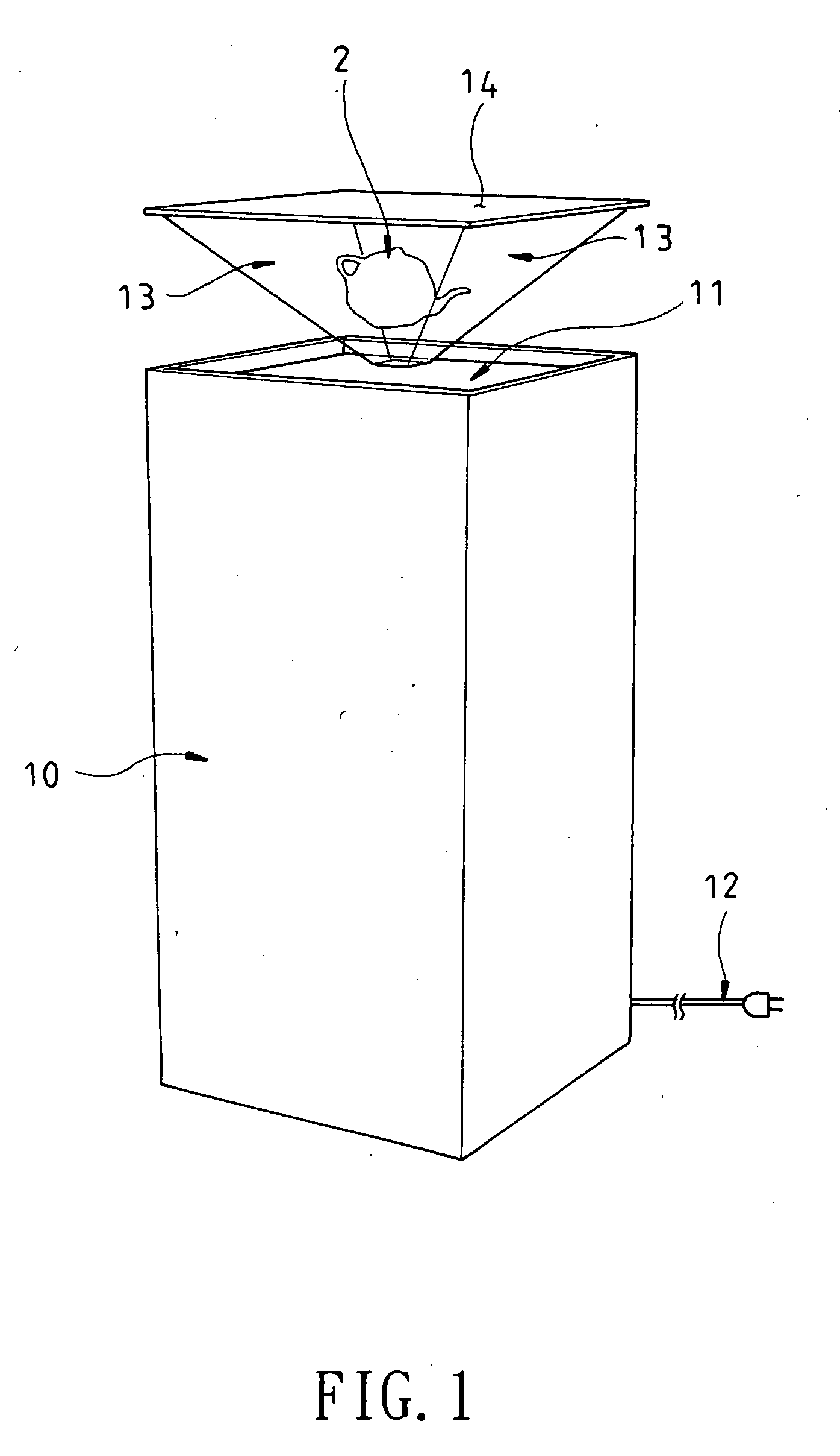
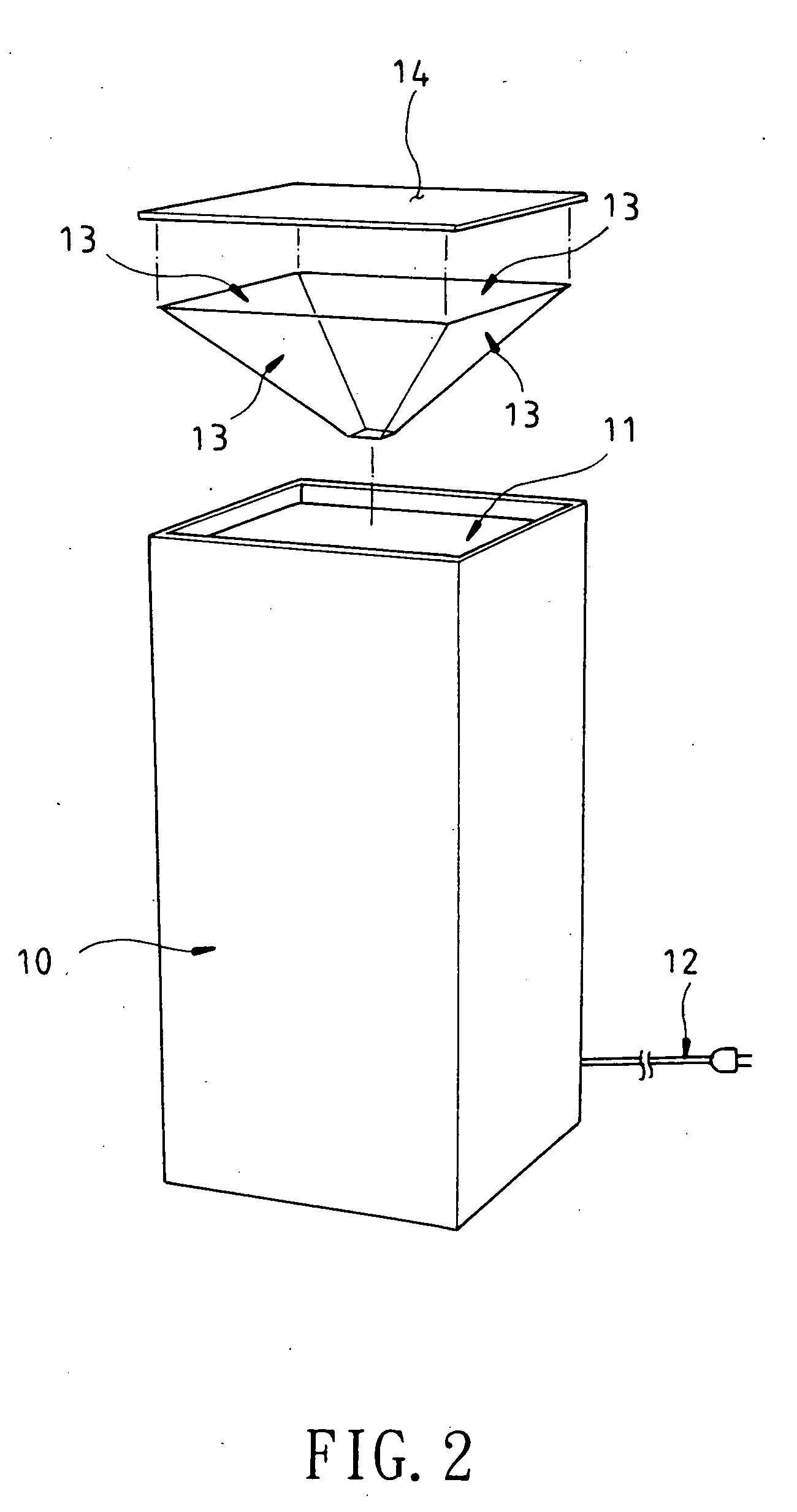
[0028]With reference to FIG. 6 together with the aforementioned components of the 3D image formation device of the present invention before the 3D image formation device is assembled, the present invention uses reflection principles to reflect four image sources onto the transparent reflecting lenses 13 that are combined into an inverted pyramid shape, so as to allow a viewer 18 to see a 3D image floating in the air 2 from any angle. Due to a specific reflecting angle of the present invention, the viewer 18 can see one image at a time from the same angle. For dynamic and rotating or moving images, a more lively 3D perception effect of the images can be achieved.

[0029]With reference to FIGS. 7 to 10 for a 3D image formation device in accordance with another preferred embodiment of the present invention, the 3D image formation device comprises a mounting box 30, an image source device 31, a transparent reflecting lens 33 and a back panel 34.

[0030]The mounting box 30 is substantially a...


PUM


Abstract

A three-dimensional 3D image formation device includes a mounting box, an image source device, a plurality of transparent reflecting lenses and a top panel. Reflection principles are used for reflecting a plurality of image sources of the image source device onto the transparent reflecting lenses tilted at an angle of 45 degrees, such that a viewer can view a 3D image floating in the air from any angle, and the 3D image formation device gives a lively 3D perception of the image to enhance the value of the product.

Description

BACKGROUND OF THE INVENTION[0001]1. Field of the Invention[0002]The present invention relates to a three-dimensional (3D) image formation device comprised of a mounting box, an image source device, a plurality of transparent reflecting lenses and a top panel and uses reflection principles to reflect a plurality of image sources of the image source device onto the transparent reflecting lenses tilted at 45 degrees, such that a viewer can view a 3D image floating in the air from any angle, and the invention further gives a lively 3D perception of the image to enhance the value of the product.[0003]2. Description of the Related Art[0004]In binocular vision, an object is observed from two viewing angles (or left and right eyes) simultaneously. Positions of left and right eyes are different, so that there is a slight difference between the images observed by the left and right eyes, and such difference becomes a main cause of producing 3D images.[0005]The so-called “persistence of vision...

Claims


Application Information

Patent Timeline
IPC IPC(8): G02B27/22
CPCH04N13/0488G02B27/2292A61P35/00G02B30/56H04N13/388
Inventor WANG, TSUNG-WU
Owner TENDRIL TECH
Why Eureka
Try Eureka