Lifesaving parachute

a life-saving parachute and parachutist technology, applied in parachutes, emergency apparatus, building rescue and other directions, can solve the problems of unresolved human life loss, unsafe rope or ladder, and almost impossible to use rope or ladder

Inactive Publication Date: 2009-05-28
SANDAPA KOREA CO LTD
View PDF9 Cites 18 Cited by
  • Summary
  • Abstract
  • Description
  • Claims
  • Application Information

AI Technical Summary

Benefits of technology

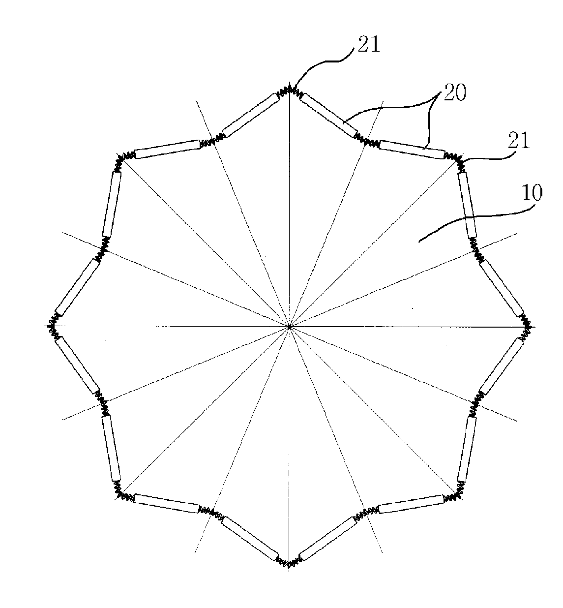
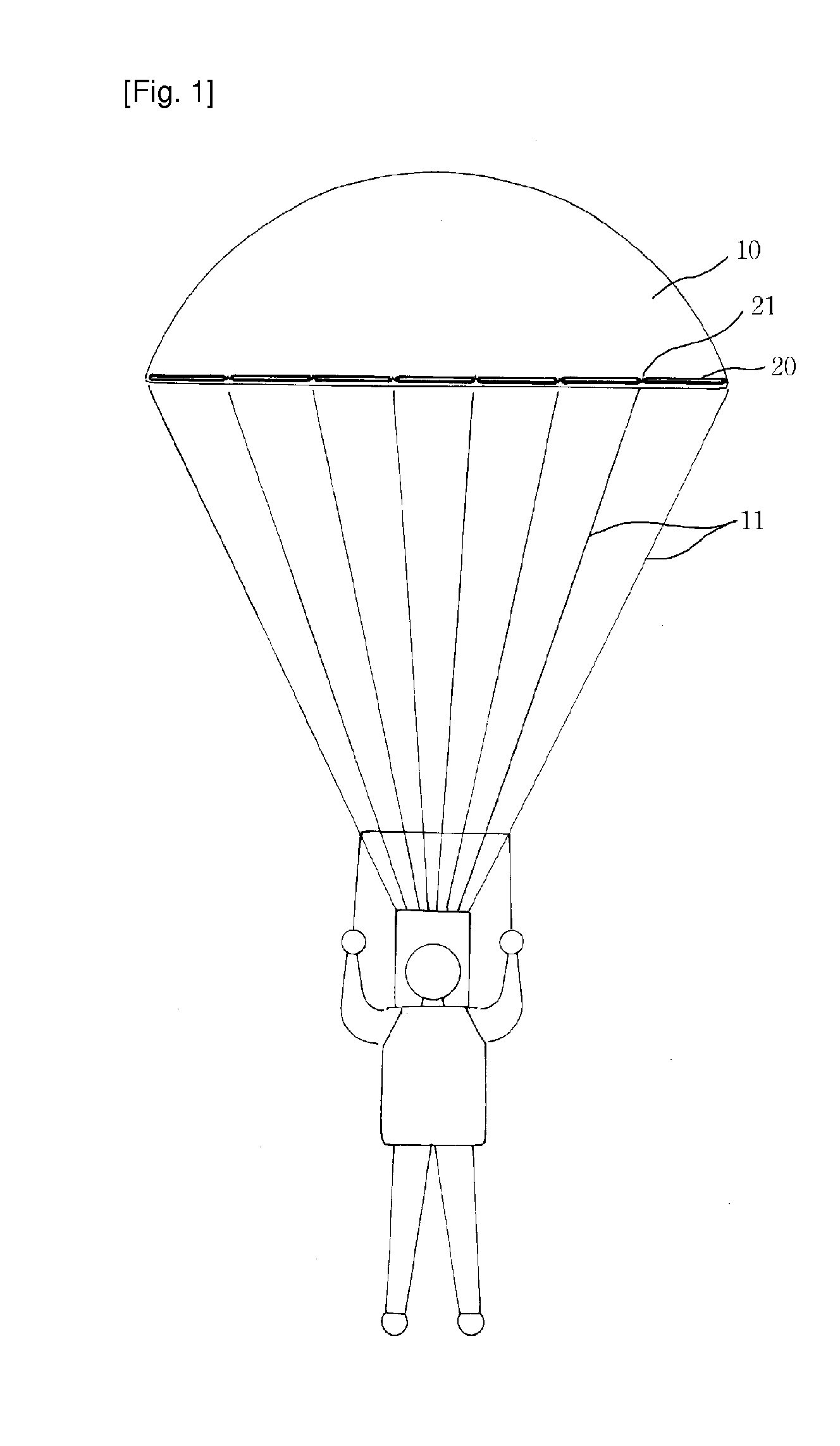
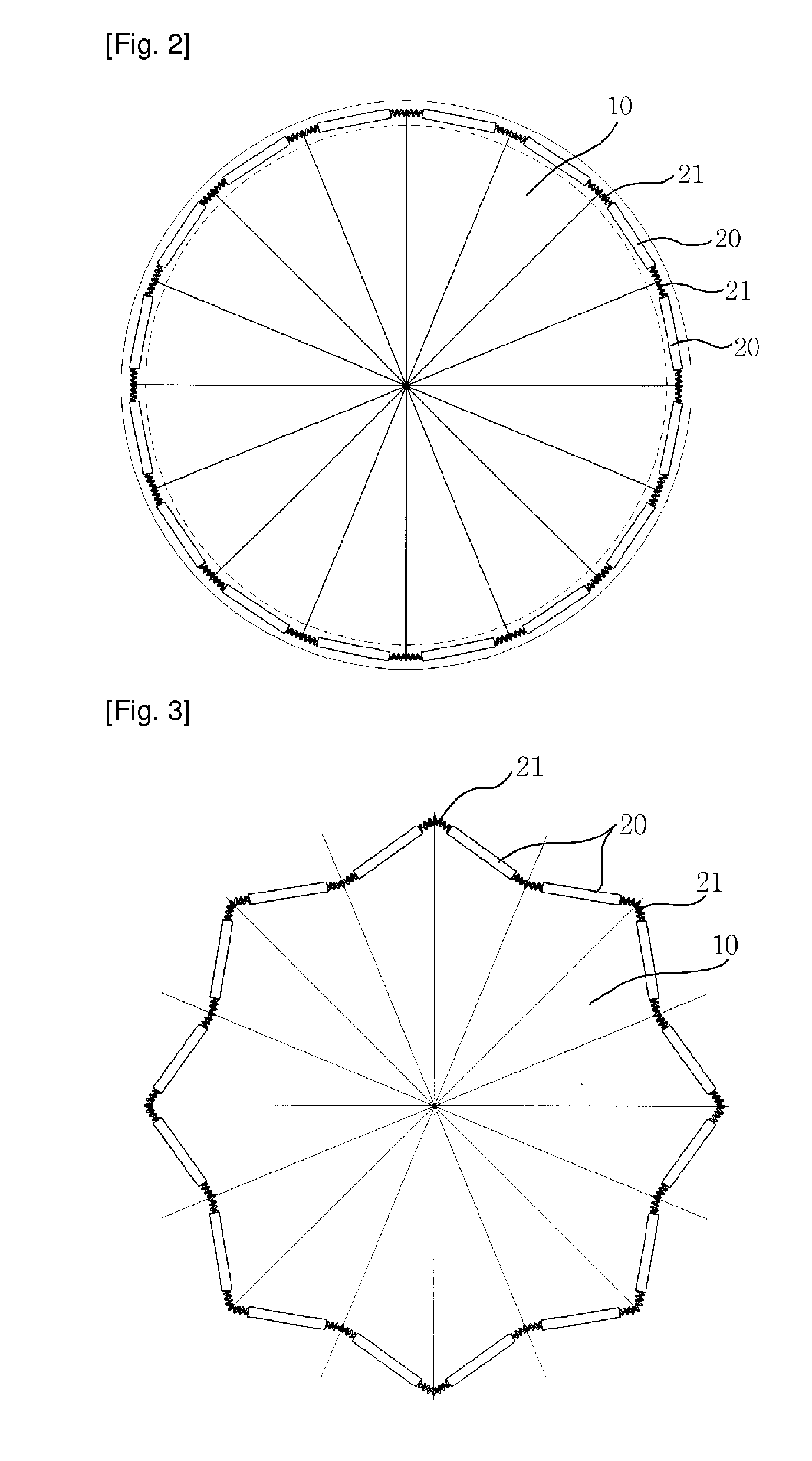
The technical effect of this patent is that it describes how a parachute can help people who are jumping out of tall buildings during an emergency situation. When the main part of the parachute separates from its container, special parts called stick elements quickly stretch out, which causes the chute to open up like a fan. This helps to slow down the person's descent while they hit the ground, making sure they don't get hurt or die from impact.

Problems solved by technology

The technical problem addressed in this patent is how to quickly and safely evacuate high-story buildings during times of emergency such as fire or earthquake, while also addressing issues related to traditional methods like slow descent via ropes or ladders, which can lead to further safety risks due to fire movement. Additionally, there are challenges when trying to utilize these methods with low-story buildings where fire or other hazards may occur.

Method used


Image

  • Lifesaving parachute
  • Lifesaving parachute
  • Lifesaving parachute

Examples


case 30

[0030]The receiving case 30 is opened at a bottom part for receiving the main body 10 as folded and injection-molded in the shape of empty receiving case.

[0031]The receiving case 30 is integrally formed with a ring 31 or connected to a strap 32 at an opposite side of the opening part for the main body 10 of the parachute to spread out in a short time in an emergency such as fire.

[0032]The ring 31 is held by a pipe such as a rail of an apartment building and helps the main body 10 to be immediately separated from the receiving case 30 when the user jumps after the user couples the hooks or buckles, which are formed at ends of the straps 11 (not shown), with his waist belt or shoulder straps.

[0033]The receiving case 30 is mounted to an outer wall of a building by holding the straps 32 to the rail of the outer wall of the building as described above, and the main body 10 is immediately separated from the receiving case 30 when the user jumps after fixing the hooks or buckles, which are...


PUM


Abstract

The present invention relates to a lifesaving parachute, for moving people in danger to the ground safely in the case of accidents causing the loss of lives, such as fire of a high-storied building, earthquake and the like, which includes a main body having straps for a user to wear the parachute, stick elements formed of a unit length and fixed to the main body along a periphery thereof, elastic elements connected to connection elements of the stick elements for applying elastic force to the stick elements in a spreading direction of the stick elements, and an empty receiving case having an opened lower part for receiving the main body as folded.

Description


Claims


Application Information

Patent Timeline
Owner SANDAPA KOREA CO LTD
Why Eureka
Try Eureka