Multimen brachytherapy balloon catheter

a brachytherapy and balloon catheter technology, applied in the field of multi-men brachytherapy balloon catheters, can solve the problems of reducing the treatment effect of healthy tissue, so as to reduce the damage of healthy tissue, reduce the distance between the cavity and the skin surface, and reduce the effect of radiation damag

Inactive Publication Date: 2009-07-30
HOLOGIC INC
View PDF84 Cites 30 Cited by
  • Summary
  • Abstract
  • Description
  • Claims
  • Application Information

AI Technical Summary

Benefits of technology

[0016]A method for treating a body cavity or other intracorporeal site of a patient includes delivering a treatment agent such as a radiation source to a body cavity to treat the desired tissue while minimizing damaging irradiation of healthy tissues. More specifically, a method for treating a body cavity or intracorporeal site includes providing a device having an elongate shaft with a proximal end, a distal end, and a treatment location in a distal portion of the shaft. The method further includes providing a radiation source configured to be deposited in the treatment location and a radiation shielding component partially encircling the treatment location which is configured to control at least in part the emission of radiation emitted from the treatment location. The device is advanced within the patient until the treatment location of the device is deployed within the body cavity or site and the radiation source is positioned within the treatment location. The radiation shielding component is positioned to shield portions of the body cavity from radiation emitted from the radiation source.
[0017]A patient's skin is susceptible to damage from radiation delivered by isotopes (e.g. seeds) or x-ray catheters in a lumen of a radiation balloon catheter if the radiation source is too close to the skin. Generally, radiation treatments using a radiation balloon catheter is usually not performed on patients where the body cavity (e.g. from a lumpectomy) is less than 5 mm, sometimes less than 7 mm from the patient's skin. Additionally, over inflation of the balloon can thin and stretch the skin. The application of a vacuum to the body cavity can help by pulling the tissue to the balloon and increased cavity to skin surface distances would result. However, in some instances it would still be too thin to treat. The number of potential patient's which are suitable candidates for treatments with the present device is significantly increased due to reducing the potential for skin tissue damage.
[0018]The surface (inside or outside) of the balloon or within the balloon wall may be provided with indicator marks for location or orientation detection during the procedures. For example, dots or lines to help place balloon in appropriate position under CT, x-ray or fluoroscopy. The indicator marks may be radiopaque. Alternatively, or additionally, ultrasound indicators or MRI and direct visual indicators could be incorporated. The indicator marks may extend along the catheter shaft to help with placement of the catheter device during the treatment procedure and the orientation of the off-set lumen and shield.
[0019]One attractive additional feature for brachytherapy for breast lumpectomy sites is to provide heat to the tissue lining of the cavity either simultaneously with or sequentially to (before or after) irradiation. Suitable means to do this are described in U.S. Pat. No. 5,106,360 (Ishiwara et al.) wherein brachytherapy catheter is provided with heating electrical coils in the treatment region of the catheter. Other means such as inflation fluid at elevated temperatures may be employed. Generally, tissue temperature must be less than 100°, preferably less than 60° C. to avoid excess damage to surrounding health tissue.

Problems solved by technology

However, radiation, chemotherapy, thermal treatment, and other cancer treatments often have deleterious effects on healthy tissue in addition to the desired effects on cancerous tissue.
Tissue cavities typically are not uniform or regular in their sizes and shapes, so that differences in dosages applied to different regions of surrounding tissue, including “hot spots” and regions of relatively low dosage, often result from radiation treatment.
However, some of these catheter constructions are complex and difficult to manufacture.

Method used


Image

  • Multimen brachytherapy balloon catheter
  • Multimen brachytherapy balloon catheter
  • Multimen brachytherapy balloon catheter

Examples


Embodiment Construction

[0030]The present invention is directed to devices and methods for treatment of a patient's body cavity, particularly to deliver asymmetrical radiation into a body cavity such as a cavity left after removal of tissue from the site. While the detailed description is directed to a device configured for treating a patient' breast after tissue removal such as in a lumpectomy, other body sites may also be treated with the device.

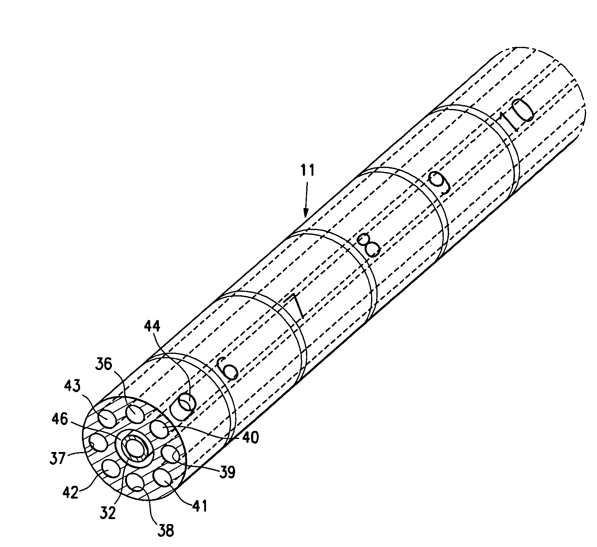
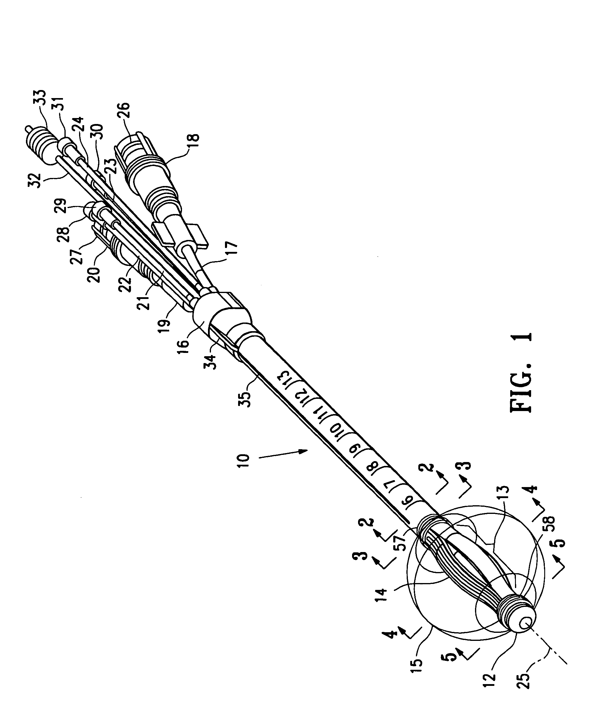
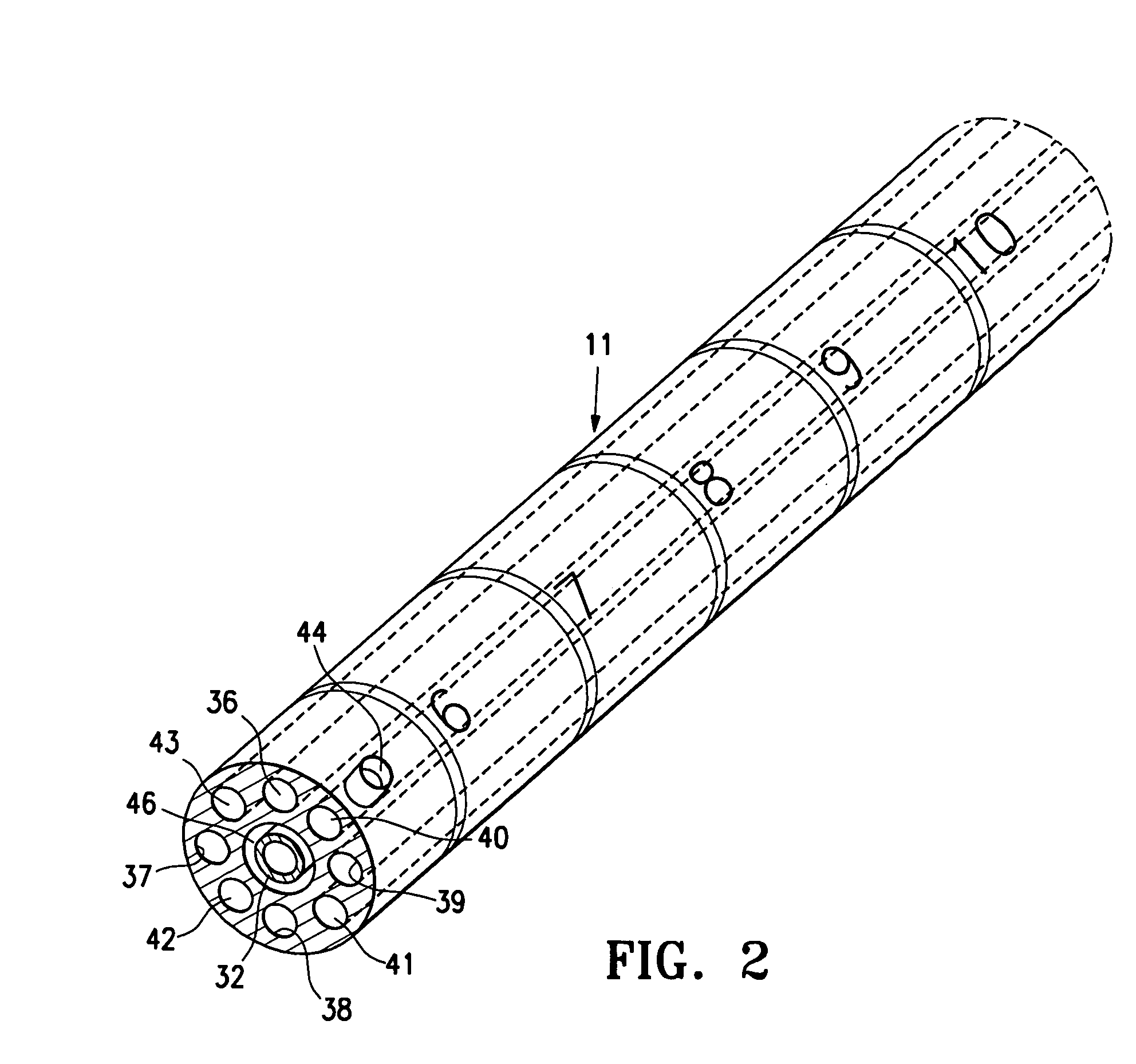
[0031]FIGS. 1-8 illustrate a brachytherapy catheter device 10 embodying features of the invention which has an elongated shaft 11, a distal tip 12, a treatment location 13 in a distal shaft portion 14 proximal to the distal tip. The device 10 has a balloon 15 on the distal shaft portion 14 which surrounds the treatment location 13. A hub 16 is mounted on the proximal end of the shaft 11 which has an inflation line 17 with leur connection 18, a vacuum line 19 with a leur connection 20 and four outer delivery tubes 21, 22, 23, 24 for delivery of a radiation source ...


PUM

PropertyMeasurementUnit
temperatureaaaaaaaaaa
flexibleaaaaaaaaaa
sizesaaaaaaaaaa

Abstract

The disclosure describes a device for asymmetrical irradiation of a body cavity or site, such as after removal of tissue, e.g. biopsy or lumpectomy. The device includes an elongated tubular shaft having an inner lumen and a tubular wall with a plurality of lumens extending within the wall which are configured for receiving a radiation source. The distal portion of the tubular shaft is cut into a plurality of longitudinally separated wall segments with a lumen extending within at least one of the wall segments. A support member is positioned within the separated wall segments to support and position the wall segments in a desired configuration for brachytherapy. An expandable member such as an inflatable balloon is mounted on the distal shaft portion about the separated wall segments wall which when inflated secures the distal shaft portion within a desired intracorporeal site for brachytherapy treatment.

Description

RELATED APPLICATIONS[0001]This application is related to provisional application Ser. No. 61 / 062,179, filed on Jan. 24, 2008, which is incorporated herein in its entirety and which is relied upon for priority.FIELD OF THE INVENTION[0002]This invention generally relates to devices and methods for treating tissue surrounding a body cavity, such as a site from which cancerous, pre-cancerous, or other tissue has been removed.BACKGROUND OF THE INVENTION[0003]In diagnosing and treating certain medical conditions, it is often desirable to perform a biopsy, in which a specimen or sample of tissue is removed for pathological examination, tests and analysis. A biopsy typically results in a biopsy cavity occupying the space formerly occupied by the tissue that was removed. As is known, obtaining a tissue sample by biopsy and the subsequent examination are typically employed in the diagnosis of cancers and other malignant tumors, or to confirm that a suspected lesion or tumor is not malignant. ...

Claims


Application Information

Patent Timeline
Patent Type & Authority Applications(United States)
IPC IPC(8): B23P11/00
CPCA61N2005/1018Y10T29/49826A61M2025/0036A61M2025/004A61N1/403A61M25/1034A61M25/1036A61N5/1015A61F7/123A61M25/10
Inventor ACOSTA, GEORGE M.LUBOCK, PAUL
Owner HOLOGIC INC
Why Eureka
Try Eureka