Doctor blade system

a blade system and blade technology, applied in the field of blade systems, can solve the problems of reducing affecting the quality of the resultant printed product, and achieving only through the use of costly and complicated coatings, etc., to achieve uniform load application, facilitate linear adjustment, and great structural rigidity

Inactive Publication Date: 2009-10-29
KOENIG & BAUER AG
View PDF5 Cites 12 Cited by
  • Summary
  • Abstract
  • Description
  • Claims
  • Application Information

AI Technical Summary

Benefits of technology

[0017]Even a further object of the present invention is to provide a doctor blade system having great structural rigidity.
[0018]Still yet another object of the present invention is to provide a doctor blade system which facilitates linear adjustment of the doctor blade chamber with uniform load application on both blades.
[0019]Yet still a further object of the present invention is to provide a doctor blade system which is structured to facilitate exchange of the anilox roller without removal of the doctor blade system from a press assembly.

Problems solved by technology

Either too little ink, too much ink or an unequal ink thickness along the axial length of the anilox roller will cause degradation of the quality of the resultant printed product.
A traditional metal doctor blade chamber becomes too heavy to be usable.
While an aluminum or an iron material can be imbued with similar resistance properties, this can be accomplished only through the use of costly and complicated coatings.
Such coating are always subject to mechanical damage, such as chipping and scratching.
The so-coated aluminum or iron doctor blade chambers are still very heavy and are thus difficult to mount, dismount and handle.
Their primary limitation is a lack of structural rigidity, when compared with the previously used metal doctor blade chambers.
The lack of structural rigidity results in twisting and bending of the doctor blade chamber across the width of the anilox roller.
The result of such non-uniform contact force is variance in the ink thickness application to the anilox roller, uneven wear of the doctor blades, premature end seal failures and other undesirable consequences.
This is apt to result in a transverse deflection of the supporting shaft and of the doctor blade chamber.
As discussed above, such a deflection results in distortion of the GRP doctor blade chamber, a twisting of the blade system and premature wear of the end seals.
Another limitation of this prior system is that the working doctor blade is located closer to the axis of rotation of the anilox roller than is the closing doctor blade.
The working doctor blade is thus subjected to greater wear and tear than is the closing doctor blade.
As a result, more frequent maintenance is apt to be required.

Method used


Image

  • Doctor blade system
  • Doctor blade system
  • Doctor blade system

Examples


Embodiment Construction

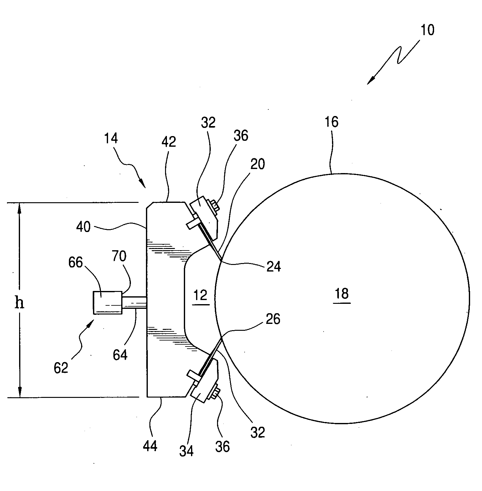
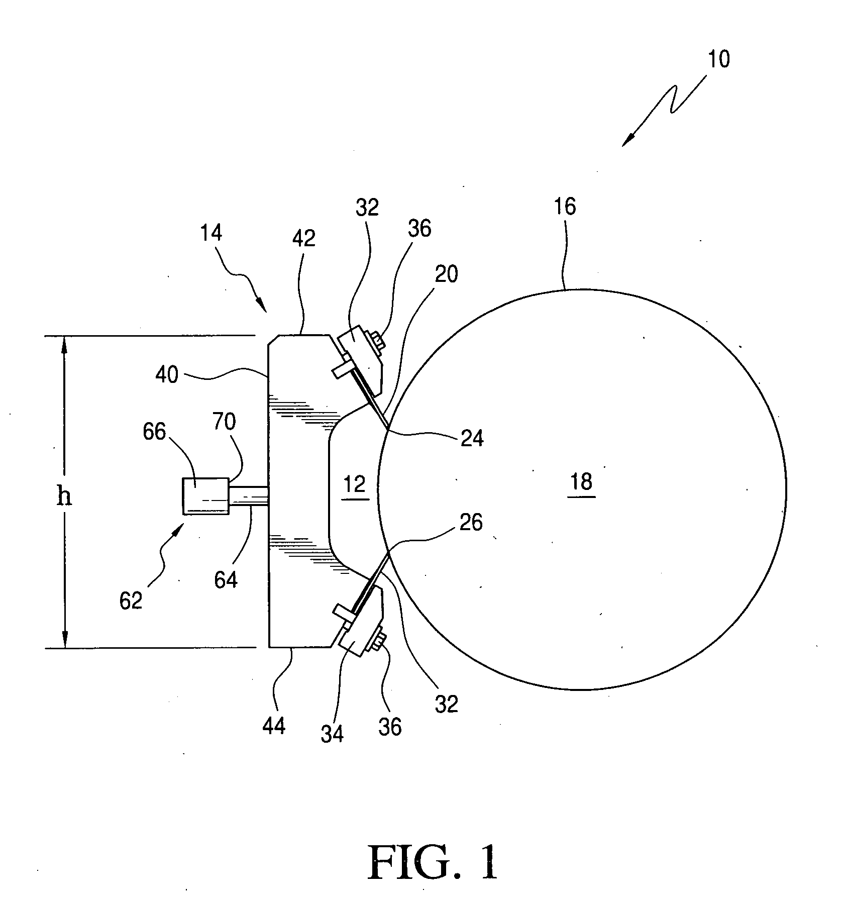
[0038]Referring initially to FIG. 1, and taken in conjunction with FIG. 2, there may be seen, generally at 10, a preferred embodiment of a doctor blade system in accordance with the present invention. It will be understood that doctor blade system, generally at 10, is intended for use primarily in a flexographic printing system or in other generally well known printing systems. In such systems printing ink is supplied to an ink reservoir 12 in a doctor blade chamber, generally at 14. That ink is then transferred to the surface 16 of an ink roller, such as an anilox roller 18.

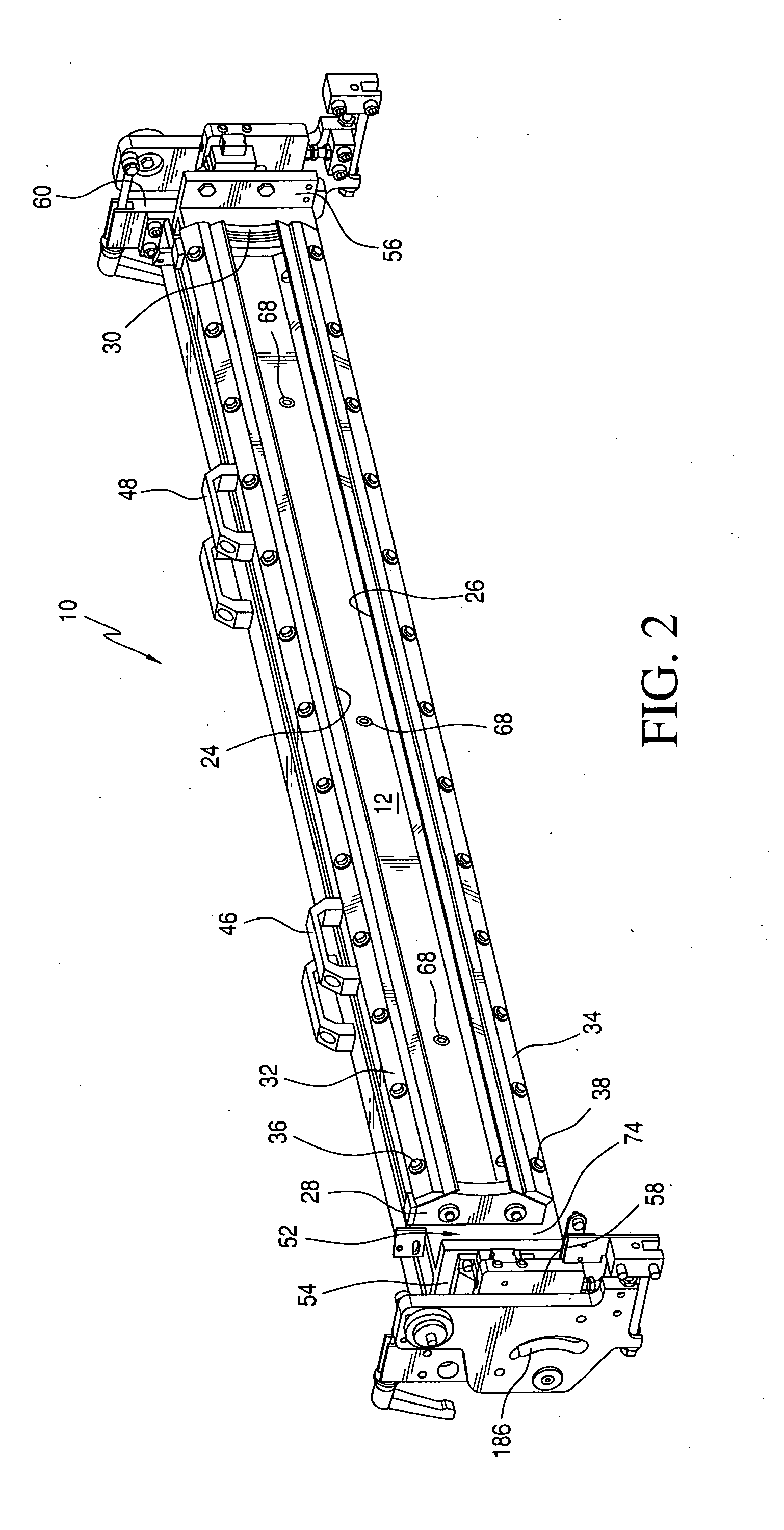
[0039]As is well known in the art, a doctor blade chamber, generally at 14 includes a working doctor blade 20 and a closing doctor blade 22 whose outer edges 24; 26, respectively, engage the surface 18 of the anilox roller 18. Suitable end plates 28 and 30, as seen more clearly in FIG. 2 cooperate with the working doctor blade 20 and the closing doctor blade 22 to define the ink reservoir 12. Seals are placed in...


PUM


Abstract

A doctor blade system utilizes a lightweight doctor blade chamber to apply ink to an inking roller. The doctor blade chamber is removably positioned on a support plate which is, in turn, carried by linear guides on pivotable end plates. A rigid box beam is also attached to the end plates and is spaced from the support plate. A plurality of membrane cylinders are mounted on the rigid box beam and engage a surface of the support plate opposite to the surface that supports the doctor blade chamber. Through the application of suitable force, the support plate and its supported doctor blade chamber can be moved, by sliding motion on the linear slides, into uniform engagement with the surface of the ink roller. The system uses pivotable end plates which are supported by exterior plates that are, in turn, pivotably supported by press side frames. The chamber doctor blade and its support plate and box beam can be moved into several different positions, with respect to the cooperating ink roller, to facilitate doctor blade chamber cleaning or replacement or ink roller replacement.

Description

FIELD OF THE INVENTION[0001]The present invention is directed generally to a doctor blade system. More particularly, the present invention is directed to a doctor blade system for use in a rotary printing press. Most specifically, the present invention is directed to a doctor blade system for use in a flexographic printing machine. The doctor blade system includes a doctor blade chamber of a light material. A full length support plate carries the doctor blade chamber. That support plate is biased across its width, in the axial direction of a cooperating anilox roller, by a plurality of membrane cylinders. Those several membrane cylinders are secured to a rigid cross member. The result is a lightweight doctor blade chamber which is not subject to the bending and distortion problems that have been prevalent in previous devices.BACKGROUND OF THE INVENTION[0002]In the field of rotary printing machines, it is generally well known to provide an inking unit that is equipped with a chamber ...

Claims


Application Information

Patent Timeline
Patent Type & Authority Applications(United States)
IPC IPC(8): B41F31/02
CPCB41F31/027
Inventor ROTHLEIN, EWALDSCHMIDT, HELMUT
Owner KOENIG & BAUER AG
Why Eureka
Try Eureka