Lighted Image Rendering Lamp

Inactive Publication Date: 2009-12-03
HONG SEUNG BEOM
View PDF10 Cites 5 Cited by
  • Summary
  • Abstract
  • Description
  • Claims
  • Application Information

AI Technical Summary

Problems solved by technology

Moreover, illuminating apparatuses typically provide illuminated images of fixed unalterable shapes.

Method used


Image

  • Lighted Image Rendering Lamp
  • Lighted Image Rendering Lamp
  • Lighted Image Rendering Lamp

Examples


Embodiment Construction

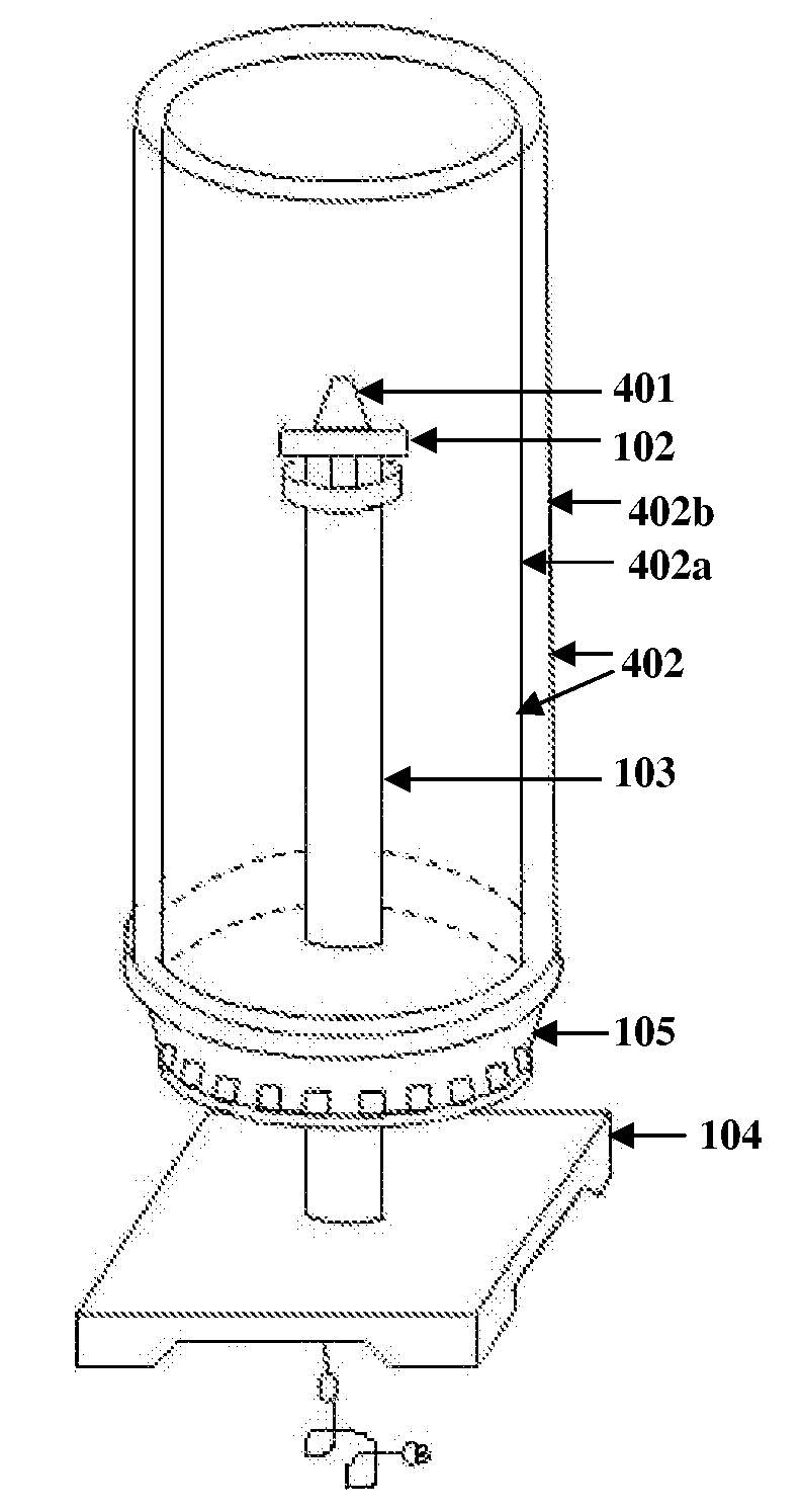
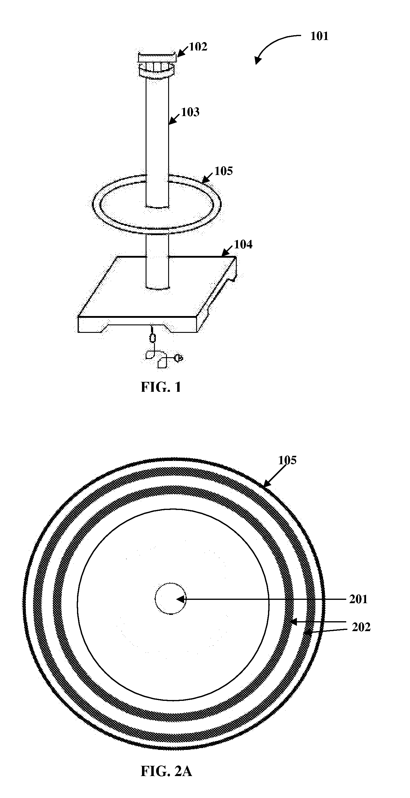
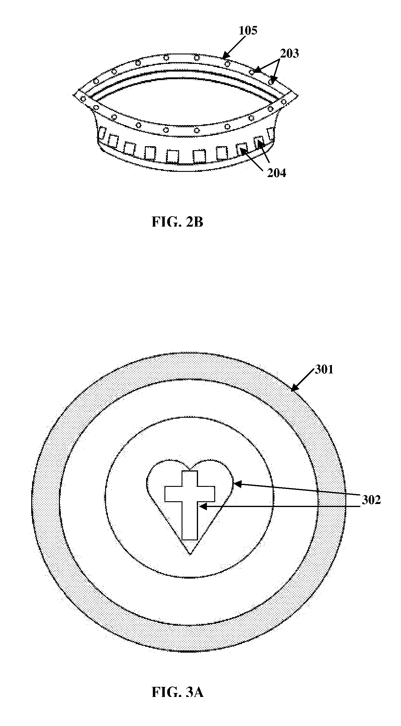
[0026]The illuminating apparatus disclosed herein renders lighted images of different shapes in different directions. The illuminating apparatus herein referred to as a “lighted image rendering lamp” comprises a lamp fixture 101, a perforated dish 105, a lamp shade 402, and a dome cover 301. FIG. 1 illustrates the lamp fixture 101. The lamp fixture 101 is of variable height. The lamp fixture 101 comprises a lamp pipe 103 with a light bulb socket 102 and a lamp base 104. The perforated dish 105 is affixed to the lamp pipe 103 by passing the lamp pipe 103 through an opening 201 in the perforated dish 105. The lamp shade 402 is affixed over the perforated dish 105, as illustrated in FIG. 4. The dome cover 301 is affixed on top of the lamp shade 402. A light bulb 401 is affixed to the light bulb socket 102, such that the light bulb 401 is enclosed within the lamp shade 402.

[0027]FIG. 2A illustrates a top view of the perforated dish 105. The perforated dish 105 comprises an opening 201 f...


PUM


Abstract

Disclosed herein is an illuminating apparatus for rendering lighted images of different shapes in different directions. The illuminating apparatus comprises a lamp fixture, a perforated dish affixed to the lamp pipe, a lamp shade affixed over the perforated dish, and a dome cover affixed on top of the lamp shade. The lamp fixture comprises a light bulb socket, a lamp pipe, and a lamp base. A light bulb is affixed to the light bulb socket and enclosed within the lamp shade. The dome cover comprises multiple inscriptions. The lamp shade comprises a layered mesh. The layered mesh may comprise wires crossing at right angles. On lighting the light bulb, the light passes through the perforations of the perforated dish, the inscriptions of the dome cover, and between the wires of the layered mesh, thereby rendering the lighted images of the different shapes in different directions.

Description

BACKGROUND[0001]This invention, in general, relates to the field of illuminating apparatuses. More specifically, this invention relates to an illuminating apparatus for providing lighted images of different shapes in different directions.[0002]Illuminating apparatuses are used for lighting indoor and outdoor spaces. Most illuminating apparatuses provide light without shapes or images. It is desirable to have an illuminating device that renders images and shapes, for example the shape of a cross. The cross is a religious symbol of Christianity. The cross is generally seen as a representation of the crucifixion of Jesus. Along with having religious significance, the cross also holds aesthetic value. Hence it is desirable to have an apparatus that renders light in the shape of the cross. Moreover, illuminating apparatuses typically provide illuminated images of fixed unalterable shapes. Other apparatuses that provide light in patterns may only be viewed from a specific side or from par...

Claims


Application Information

Patent Timeline
Patent Type & Authority Applications(United States)
IPC IPC(8): G03B21/14
CPCF21V11/14F21V1/12Y10S362/806Y10S362/812
Inventor HONG, SEUNG-BEOM
Owner HONG SEUNG BEOM
Why Eureka
Try Eureka