
Method and apparatus for curing a thermosetting material
a technology of thermosetting material and curing method, which is applied in the field of curing method and curing apparatus, can solve the problems of inefficient autoclaves and ovens, difficult control of rapid heating, and high energy and time consumption, and achieve the effect of uniform heat transfer and better mixing of liquids
- Summary
- Abstract
- Description
- Claims
- Application Information
AI Technical Summary
Benefits of technology
Problems solved by technology
Method used
Image

Examples
Embodiment Construction
)
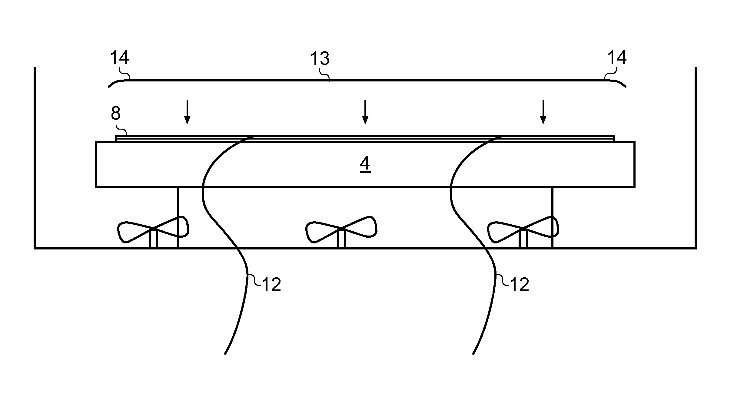
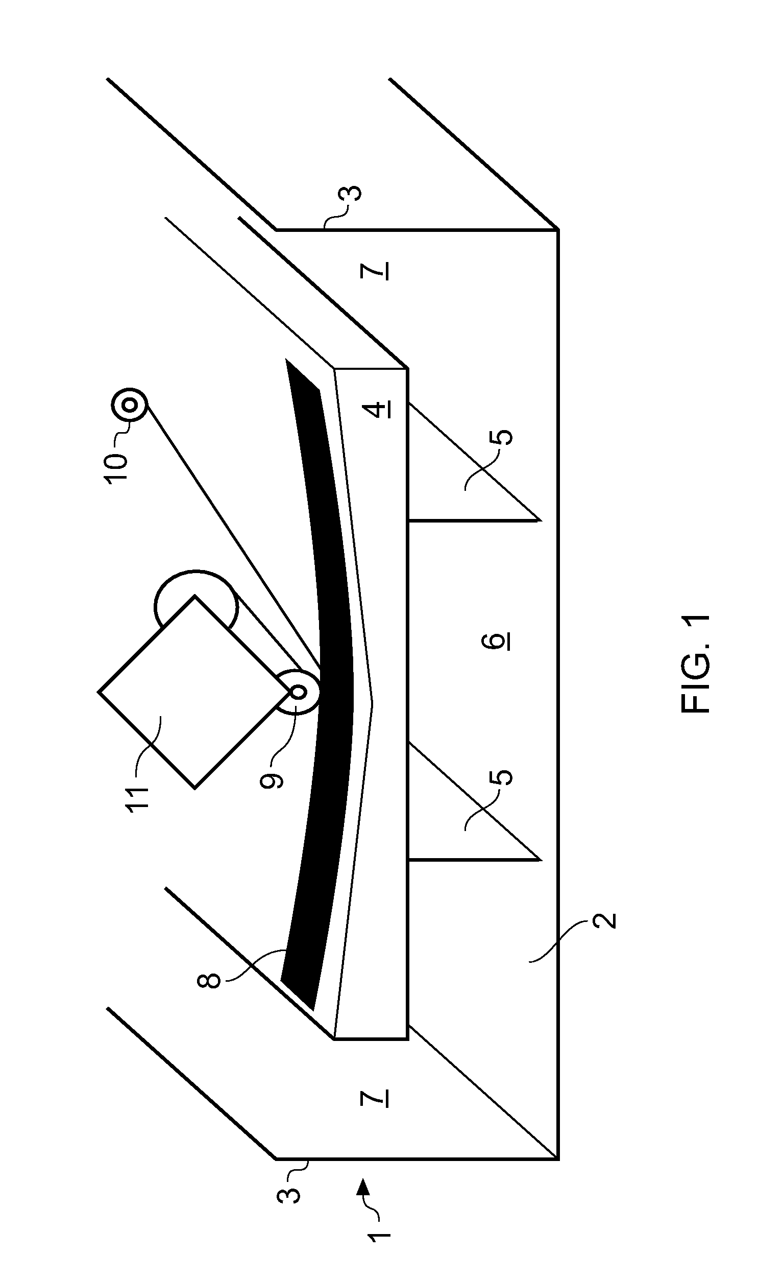
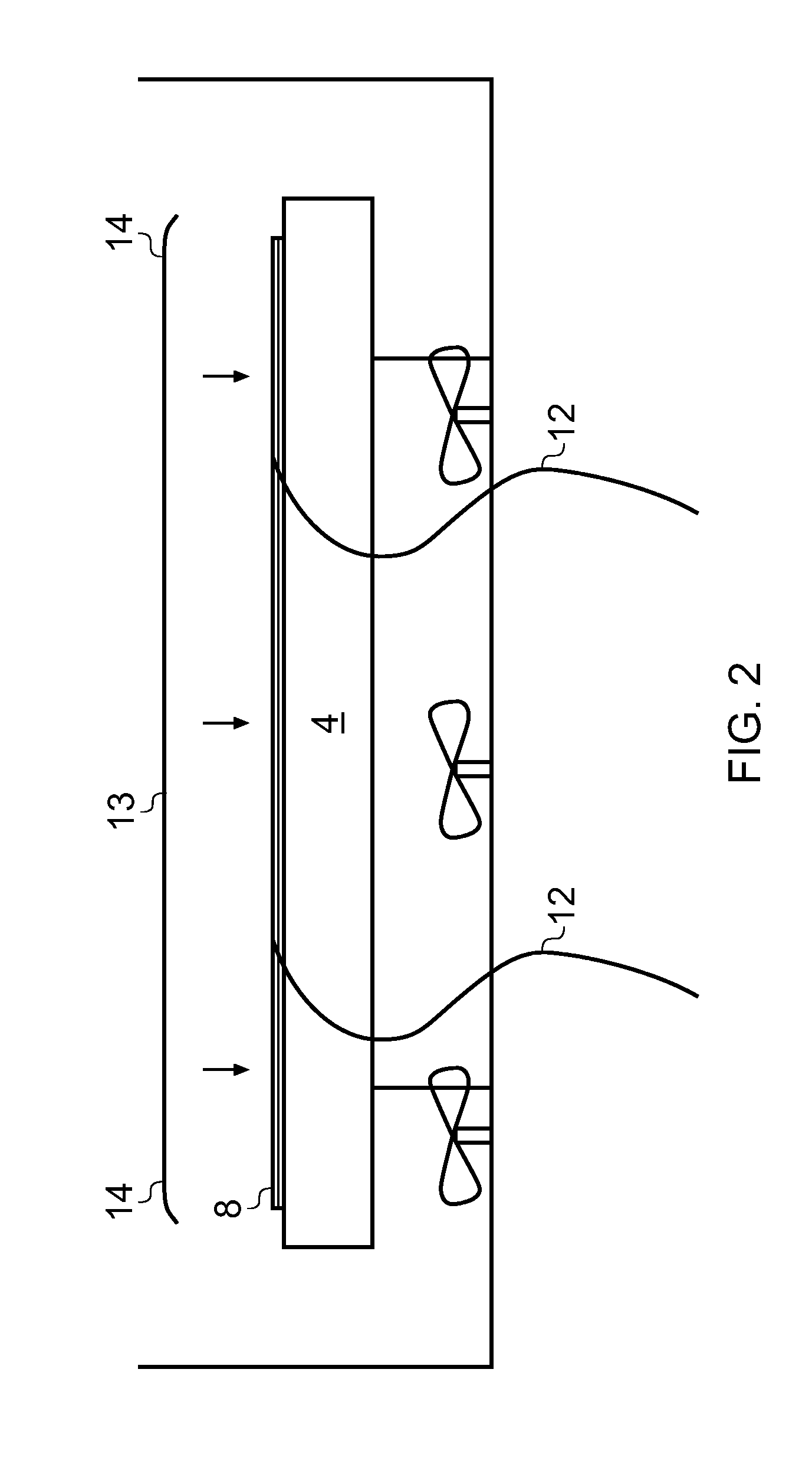
[0034]A curing tank 1 shown in FIG. 1 comprises a base 2, a pair of side walls 3 and a pair of end walls (not shown). In the case where the tank is used to cure an aircraft wing skin, the tank may be 35 m long by 5 wide.
[0035]A mould tool 4 is mounted on a pair of supports 5, with a gap 6 between the supports. Gaps 7 are also provided between the sides of the mould tool 4 and the side walls 3. The mould tool 4 may be permanently or semi-permanently fixed in place in the tank.
[0036]A composite component 8 is shown in FIG. 1, in the process of being laid onto the mould tool 4. The component 8 comprises a series of layers of uni-axial carbon-fibres, pre-impregnated with a thermosetting epoxy resin (conventionally known as “prepregs”). The prepregs are laid with their fibre directions at different angles, as required to give desired structural characteristics to the component. Each prepreg is laid by an Advanced Automatic Tape Laying (ATL) machine roller 9, and may be augmented by an U...
PUM
| Property | Measurement | Unit |
|---|---|---|
| temperature | aaaaa | aaaaa |
| cure temperature | aaaaa | aaaaa |
| temperature | aaaaa | aaaaa |
Abstract
Description
Claims
Application Information