Drying furnace for cated film

a coating film and drying furnace technology, applied in the direction of drying machines with progressive movements, furnaces, instruments, etc., can solve the problems of fixed pins and lift pins leaving traces, and achieve the effect of preventing dripping and preventing quality defects

Inactive Publication Date: 2010-07-01
ISHII HYOKI
View PDF5 Cites 10 Cited by
  • Summary
  • Abstract
  • Description
  • Claims
  • Application Information

AI Technical Summary

Benefits of technology

[0011]In addition, the feeding means is formed of a plurality of rotators and pins which radially protrude from the rotators and abut against the lower surface of the substrate, and the interval of the pins is arranged such that the pins always abut against the lower surface of the substrate when the rotators rotate. Therefore, the abutment position against the lower surface of the substrate always changes and the glass substrate can move horizontally. As a result, the heat of the hot plate heater can be transferred more uniformly so as not to leave pin traces.
[0012]In a drying furnace for a coated film of the present invention, since the abutment position against a lower surface of a substrate always changes during the drying, traces of a supporting pin do not occur as in the conventional art and the quality defect can be prevented. In addition, since uniform heating can be achieved by using upper and lower hot plate heaters as heating means, uneven drying can be prevented and leveling of the coated film and the drying can be surely conducted, thereby preventing dripping.

Problems solved by technology

However, in the drying of the coated film, when the glass substrate has been always supported by a fixed pin in a fixed position during the drying of the coated film, temperature difference between the glass substrate and the abutment perimeter of the fixed pin causes to dry the coated film unevenly and pin traces occur, thereby leading to a quality problem.
Thus, it is feared that both the fixed pin and the lift pin leave traces.

Method used


Image

  • Drying furnace for cated film
  • Drying furnace for cated film
  • Drying furnace for cated film

Examples


embodiment 1

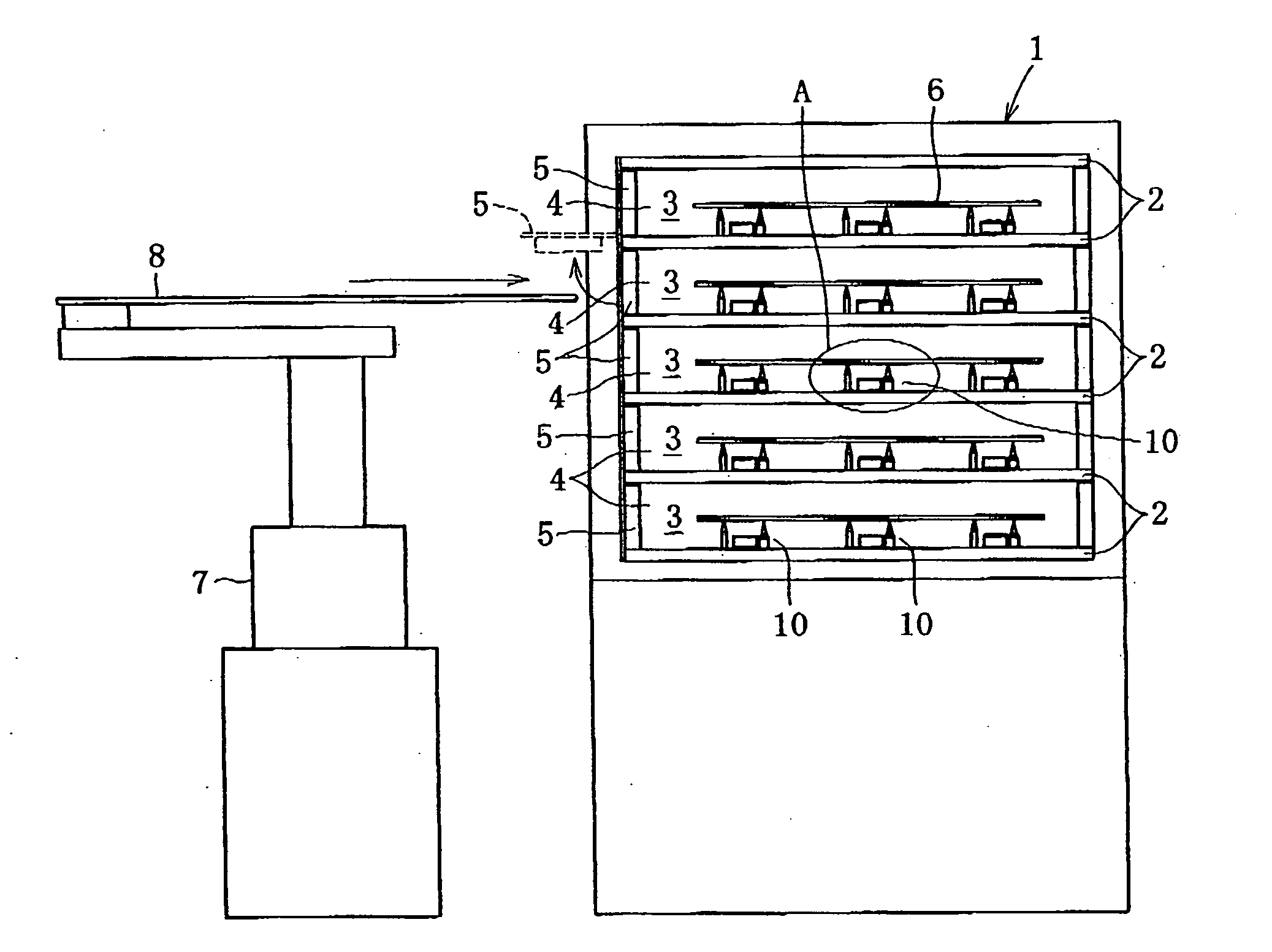
[0031]Hereinafter, Embodiment 1 of the present invention will be described with referring to FIGS. 1 to 5.

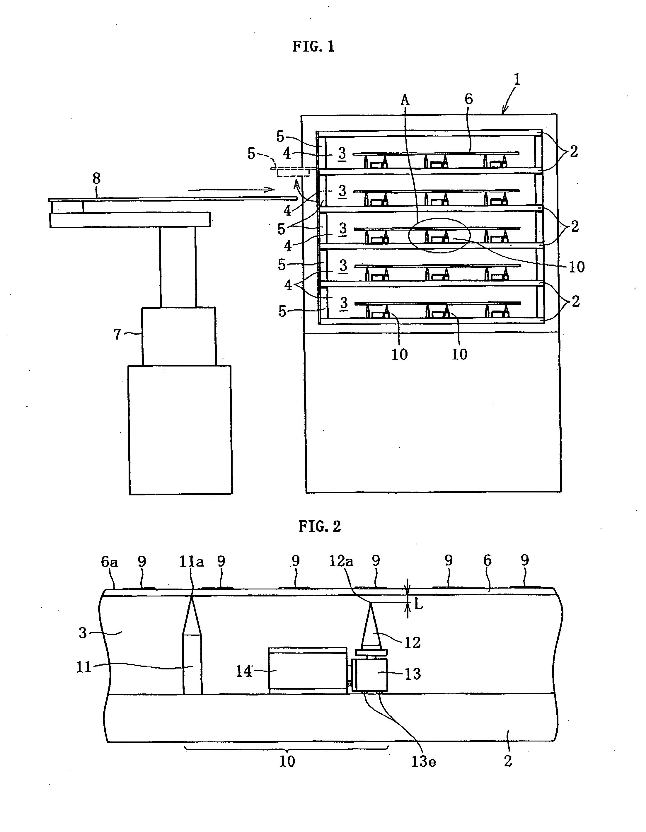
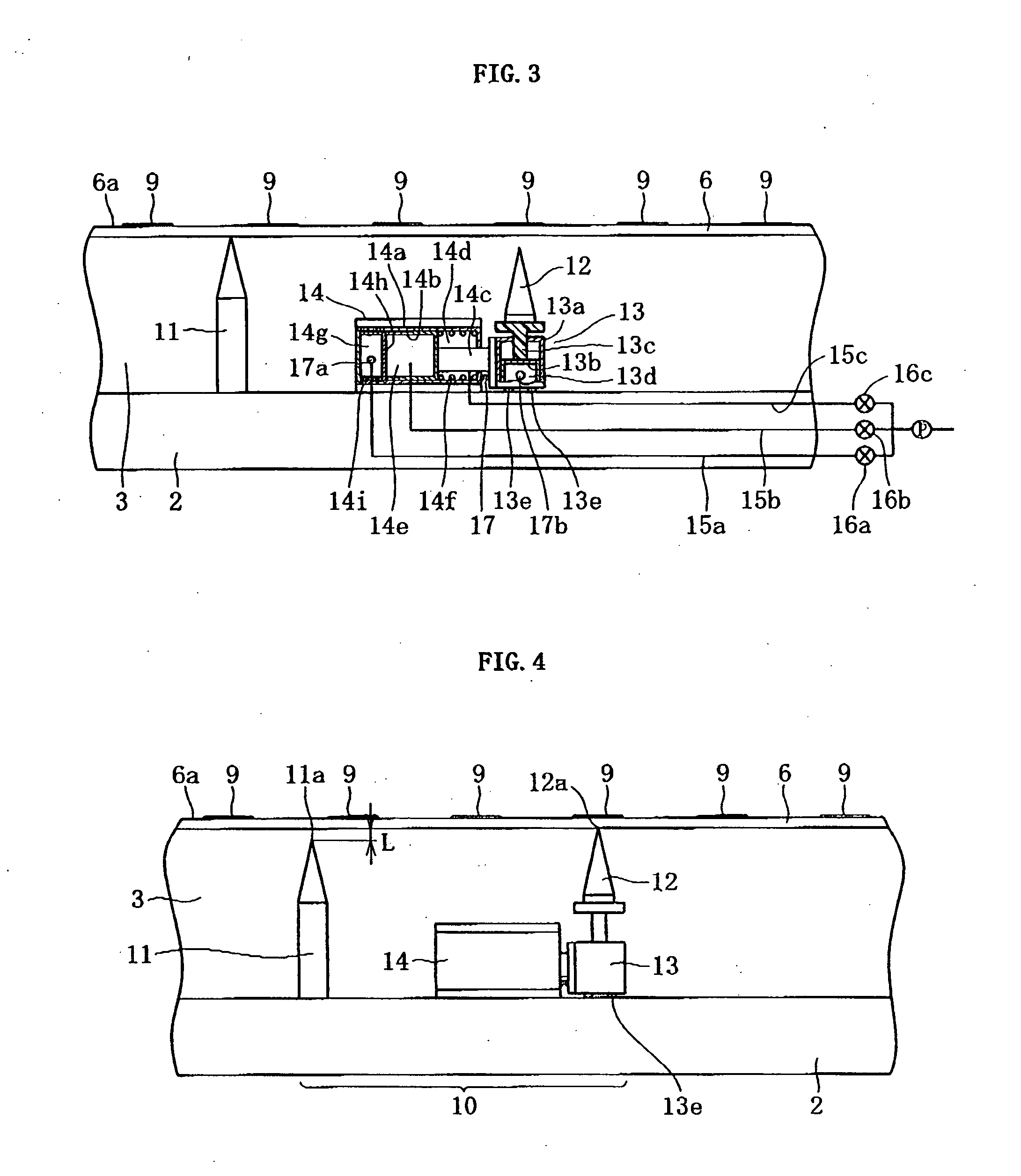
[0032]FIG. 1 is a schematic diagram of a drying furnace for a coated film illustrating Embodiment 1. FIG. 2 is an enlarged view of A part of FIG. 1. FIG. 3 is a cross-section view of FIG. 2. FIG. 4 is an explanatory drawing illustrating an operation state of a vertical expansion-and-contraction mechanism of FIG. 2. FIG. 5(a) is a diagram illustrating a state where a substrate is supported by a fixed pin when being carried in, FIG. 5(b) is a diagram illustrating a state where a moving pin moves up, FIG. 5(c) is a diagram illustrating a state where the moving pin moves horizontally, FIG. 5(d) is a diagram illustrating a state where the moving pin moves down and the substrate is supported by the fixed pin, and FIG. 5(e) is a diagram illustrating a state where the moving pin changes into a waiting state.

[0033]In the figures, a drying furnace for a coated film 1 sequentially has a ho...

embodiment 2

[0085]In addition, the material of the rotator 20 and the pin 21 in Embodiment 2 is not limited to the material disclosed, and any material can be employed as long as it has a heat resistance.


PUM

PropertyMeasurementUnit
thermal conductivityaaaaaaaaaa
moving distanceaaaaaaaaaa
radiusaaaaaaaaaa

Abstract

In drying of a glass substrate to which a coated film is applied, the heating and drying is conducted while feeding means 10, 18, which always moves on a lower surface of the glass substrate 6 to which the coated film is applied, abuts against the substrate, in order to solve a problem that when the lower surface of the coated film is supported for a long time, supporting traces occur and thereby quality of the glass substrate is reduced. With this configuration, traces of the pin 11, 12, 21 are less likely to occur.

Description

FIELD OF THE INVENTION[0001]The present invention relates to a drying furnace for a coated film on a substrate, which is a glass substrate for a liquid crystal display or a substrate for a semiconductor wafer or the like and of which surface is provided with the coated film.BACKGROUND OF THE INVENTION[0002]In recent years, in the manufacture of the liquid crystal display, thinner and larger glass substrate has been used as substrate with the aim of upsizing, producing on a large scale, and reducing thickness. In addition, a method for applying an oriented film, which serves as a coated film, to the glass substrate by an ink-jet printer has begun to be employed.[0003]However, in the drying of the coated film, when the glass substrate has been always supported by a fixed pin in a fixed position during the drying of the coated film, temperature difference between the glass substrate and the abutment perimeter of the fixed pin causes to dry the coated film unevenly and pin traces occur,...

Claims


Application Information

Patent Timeline
Patent Type & Authority Applications(United States)
IPC IPC(8): H01L21/477F26B15/00B05C9/14
CPCF26B9/06F26B25/004H01L21/67034H01L21/67109Y10S414/135G03F7/168
Inventor NAKANO, TERUYUKIKOZAWA, YASUHIRO
Owner ISHII HYOKI
Why Eureka
Try Eureka