Optical Medical Instrument

a medical instrument and optical technology, applied in the field of optical medical instruments, to achieve the effect of improving the environment of the instrument and removing the loss of hea

Active Publication Date: 2015-11-26
KARL STORZ GMBH & CO KG
View PDF2 Cites 12 Cited by
  • Summary
  • Abstract
  • Description
  • Claims
  • Application Information

AI Technical Summary

Benefits of technology

[0011]It is an object of the invention to provide an optical medical instrument in which the removal of lost heat to the environment of the instrument is improved.

Problems solved by technology

Moreover, in the prior art, it was assumed that a heat pipe can only collect heat at one end and release heat at the opposite end.

Method used


Image

  • Optical Medical Instrument
  • Optical Medical Instrument
  • Optical Medical Instrument

Examples


Embodiment Construction

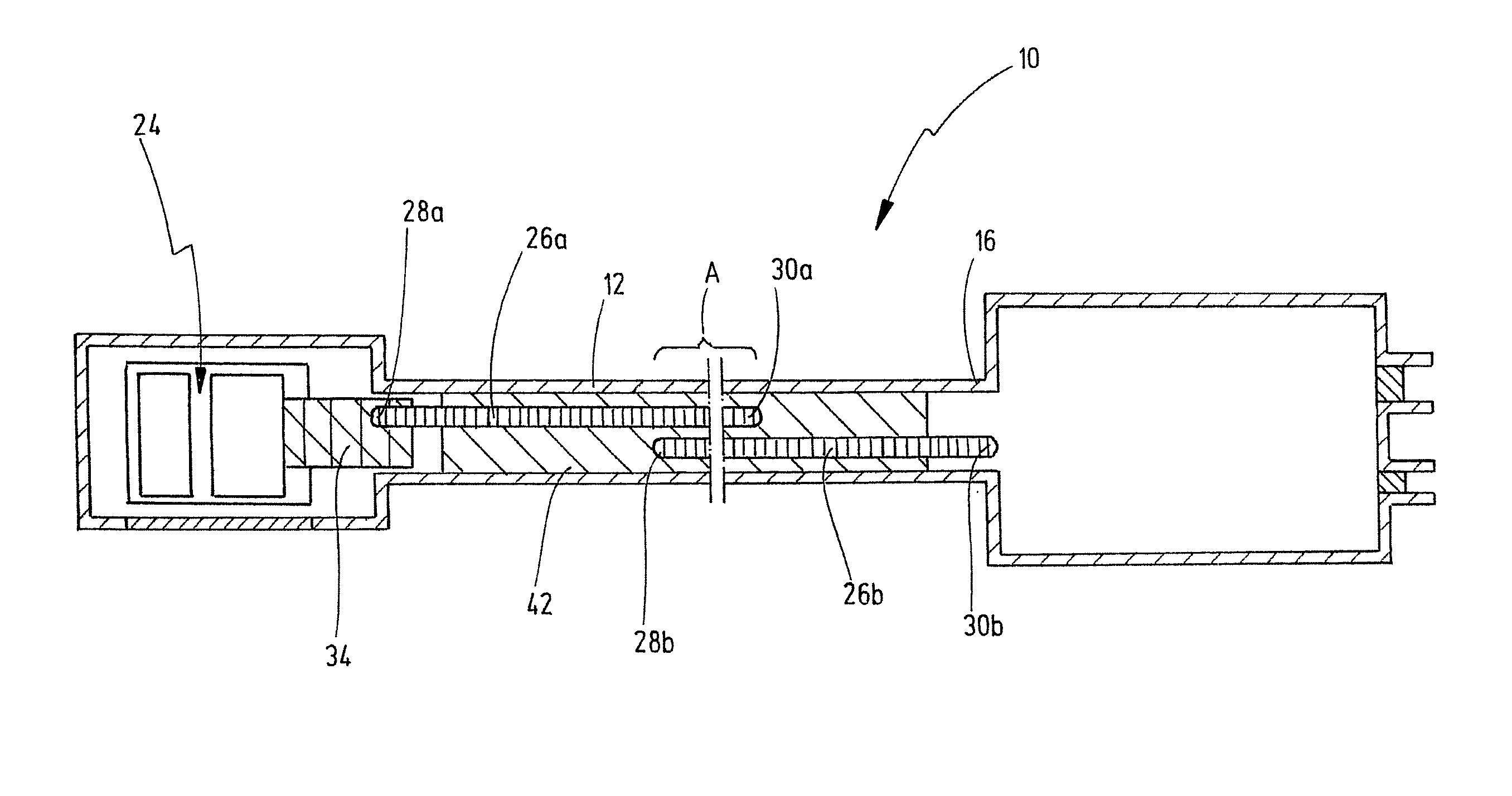
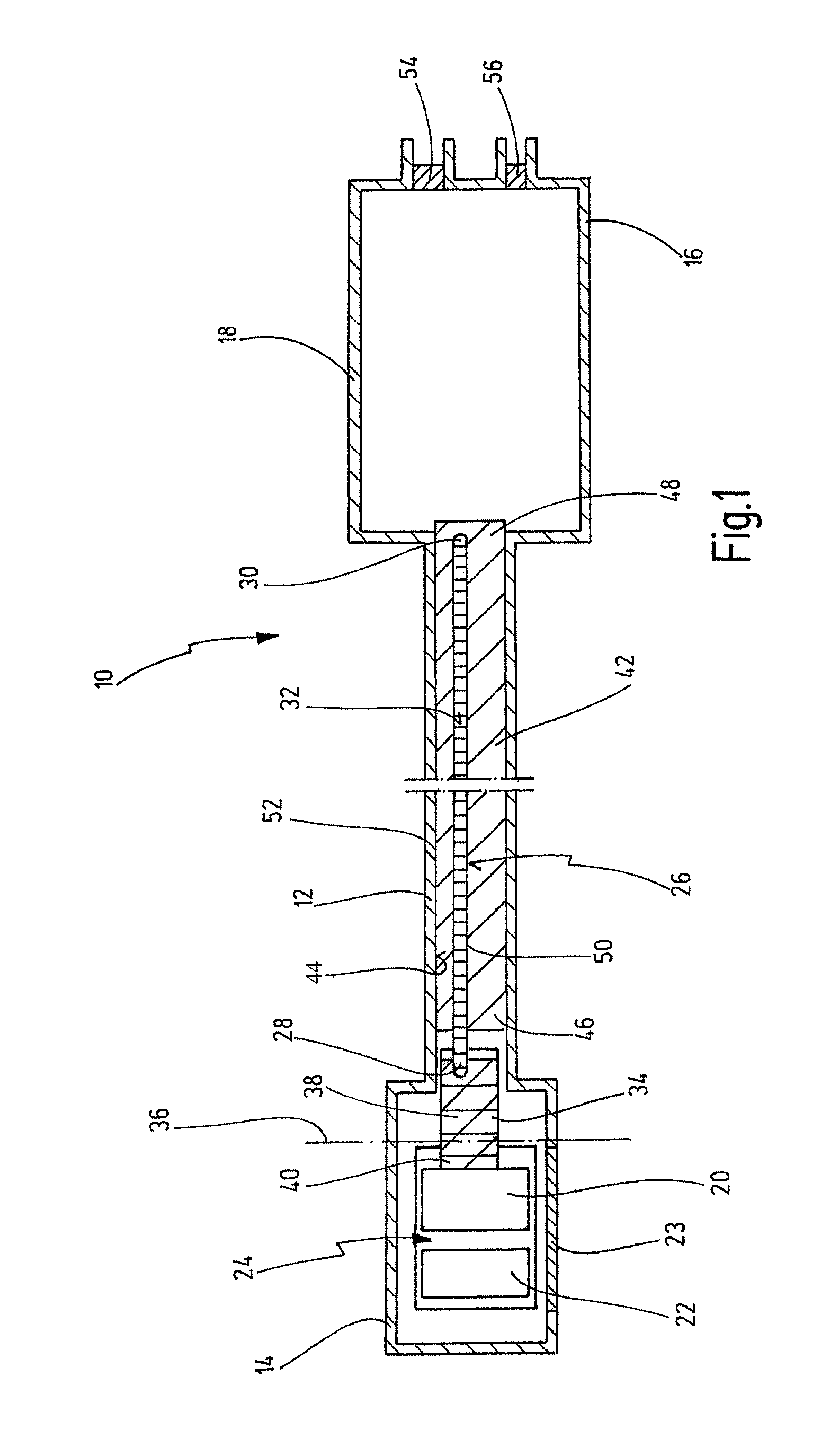
[0060]FIG. 1 shows an optical medical instrument 10 in a schematic view. The instrument 10 is an endoscope or an exoscope.

[0061]Generally, the instrument 10 has an elongate tubular shaft 12 between a distal end 14 and a proximal end 16. The shaft 12 is depicted in an interrupted view in order to show that the shaft 12 can extend over a great length. In FIG. 1, the distal end area of the instrument 10 and the proximal end area of the instrument 10 are also shown as being wider, although this is to be understood only by way of example. The proximal end 16 is designed here as an instrument head housing 18. The shaft 12 and the instrument head housing 18 constitute the housing for the components located therein. The instrument head housing 18 can belong to the shaft 12. Likewise, the shaft 12 itself is to be understood as a housing. The housing can be hermetically sealed.

[0062]The components in the shaft 12 include electronic elements arranged in the distal end area of the shaft 12, suc...


PUM


Abstract

An optical medical instrument, in particular an endoscope or exoscope, has an elongate tubular shaft, a heat source generating lost heat, and a heat pipe which extends inside the shaft, in the longitudinal direction of the shaft, and has a distal heat pipe end and a proximal heat pipe end, wherein the heat pipe is thermally coupled to the heat source in order to collect heat from the latter and remove the heat from the heat source. Between the distal heat pipe end and the proximal heat pipe end, the heat pipe is coupled thermally conductively and two-dimensionally to the shaft over at least a partial length of the heat pipe and over at least a partial circumference of the heat pipe, in order to remove heat from the heat pipe, over at least a partial length and over at least a partial circumference of the shaft, to the environment.

Description

CROSS REFERENCE TO RELATED APPLICATIONS[0001]The present application claims priority of German patent application No. 10 2014 107 205.7 filed on May 22, 2014, the whole contents of which is incorporated herein by reference.BACKGROUND OF THE INVENTION[0002]The invention relates to an optical medical instrument, in particular an endoscope or exoscope. In particular, the invention relates to an optical medical instrument of the type comprising an elongate tubular shaft, a heat source generating lost heat, a heat pipe extending inside the shaft in the longitudinal direction of the shaft and having a distal heat pipe end and a proximal heat pipe end, wherein the heat pipe is thermally coupled to the heat source in order to collect heat from the latter and remove the heat from the heat source.[0003]Endoscopes are used in the context of minimally invasive surgery as viewing instruments. The elongate shaft of an endoscope is inserted partially into the body through an artificially created o...

Claims


Application Information

Patent Timeline
Patent Type & Authority Applications(United States)
IPC IPC(8): A61B1/12A61B19/00A61B1/00
CPCA61B1/128A61B19/5212A61B1/00128A61B1/00071A61B1/0676A61B1/0684G02B23/2461G02B23/2476
Inventor PILZ, KEVINKUPFERSCHMID, MARKUSULMSCHNEIDER, DANIELHENI, ANDREAS
Owner KARL STORZ GMBH & CO KG
Why Eureka
Try Eureka