Hybrid vehicle and control method thereof

a hybrid vehicle and control method technology, applied in the direction of machine/engine, propulsion using engine-driven generators, process and machine control, etc., can solve the problem of not revealing how

Inactive Publication Date: 2010-01-14
TOYOTA JIDOSHA KK
View PDF13 Cites 70 Cited by
  • Summary
  • Abstract
  • Description
  • Claims
  • Application Information

AI Technical Summary

Benefits of technology

[0011]The target driving force setting module may set a driving force demand for driving the vehicle based on the acquired accelerator operation amount. The target driving force setting module may set the target driving force based on the set driving force demand in response to the non-satisfaction of the predetermined condition. The target driving force setting module may set the target driving force so as to gradually change in comparison with that on the non-satisfaction of the predetermined condition based on the set driving force demand and the gradual change restriction in response to the satisfaction of the predetermined condition. Thus, the target driving force is appropriately and gradually changed, so that a behavior of the hybrid vehicle can be stabilized when the shift position is changed from the neutral position to the drive position while the accelerator pedal is depressed.
[0030]According to the method, a start of the internal combustion engine may notify the driver that the accelerator operation is made while the shift position is set to the neutral position, thereby providing the driver with operational feeling same as conventional vehicles having only an internal combustion engine as a drive source. Accordingly, the hybrid vehicle can be appropriately controlled in response to the accelerator operation by the driver when the shift position is set to the neutral position.

Problems solved by technology

However, the above patent document does not disclose how to control the hybrid vehicle in these states.

Method used


Image

  • Hybrid vehicle and control method thereof
  • Hybrid vehicle and control method thereof
  • Hybrid vehicle and control method thereof

Examples


Embodiment Construction

[0045]Hereinafter, the best mode for carrying out the invention will be described with reference to embodiments.

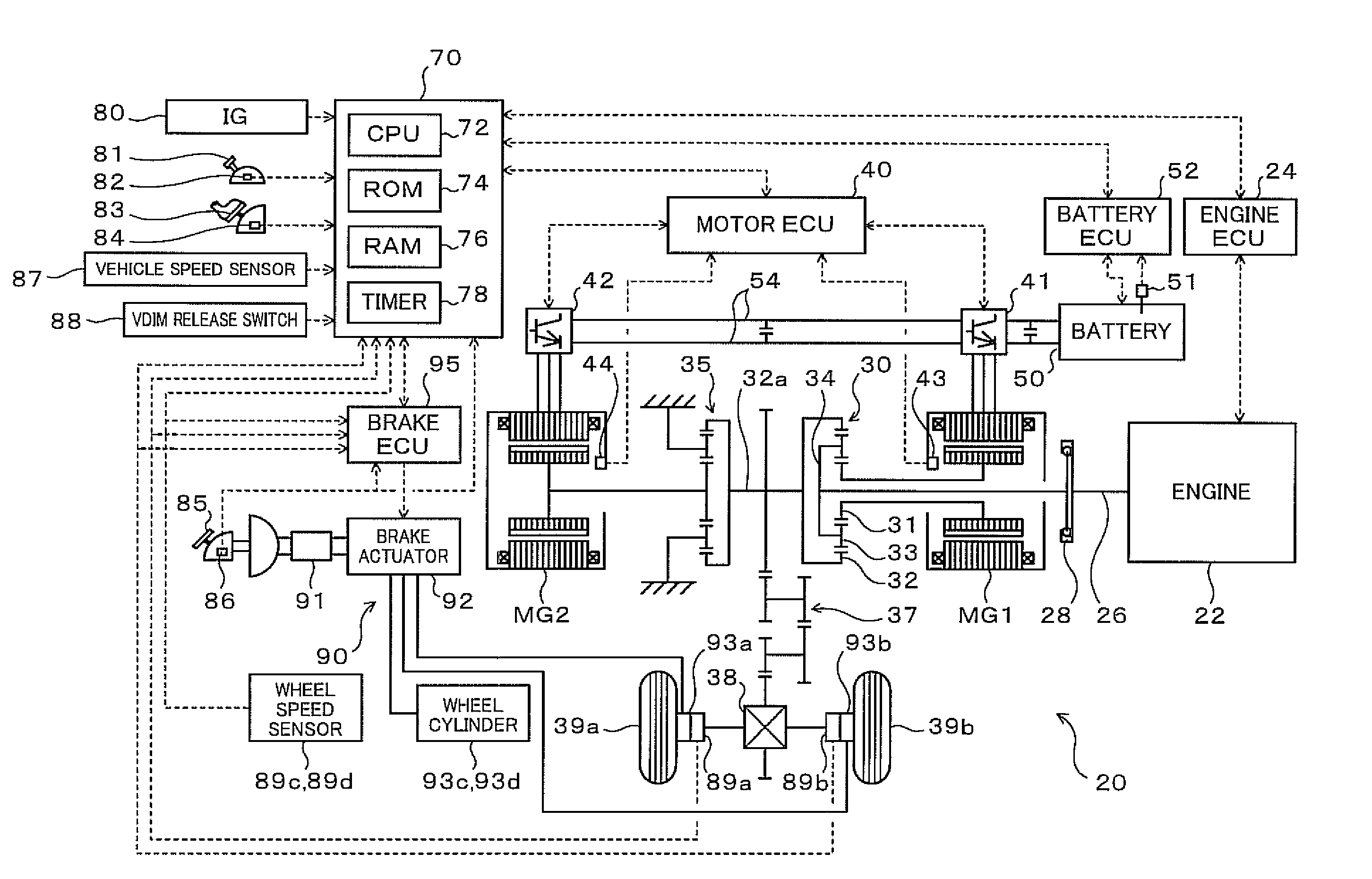
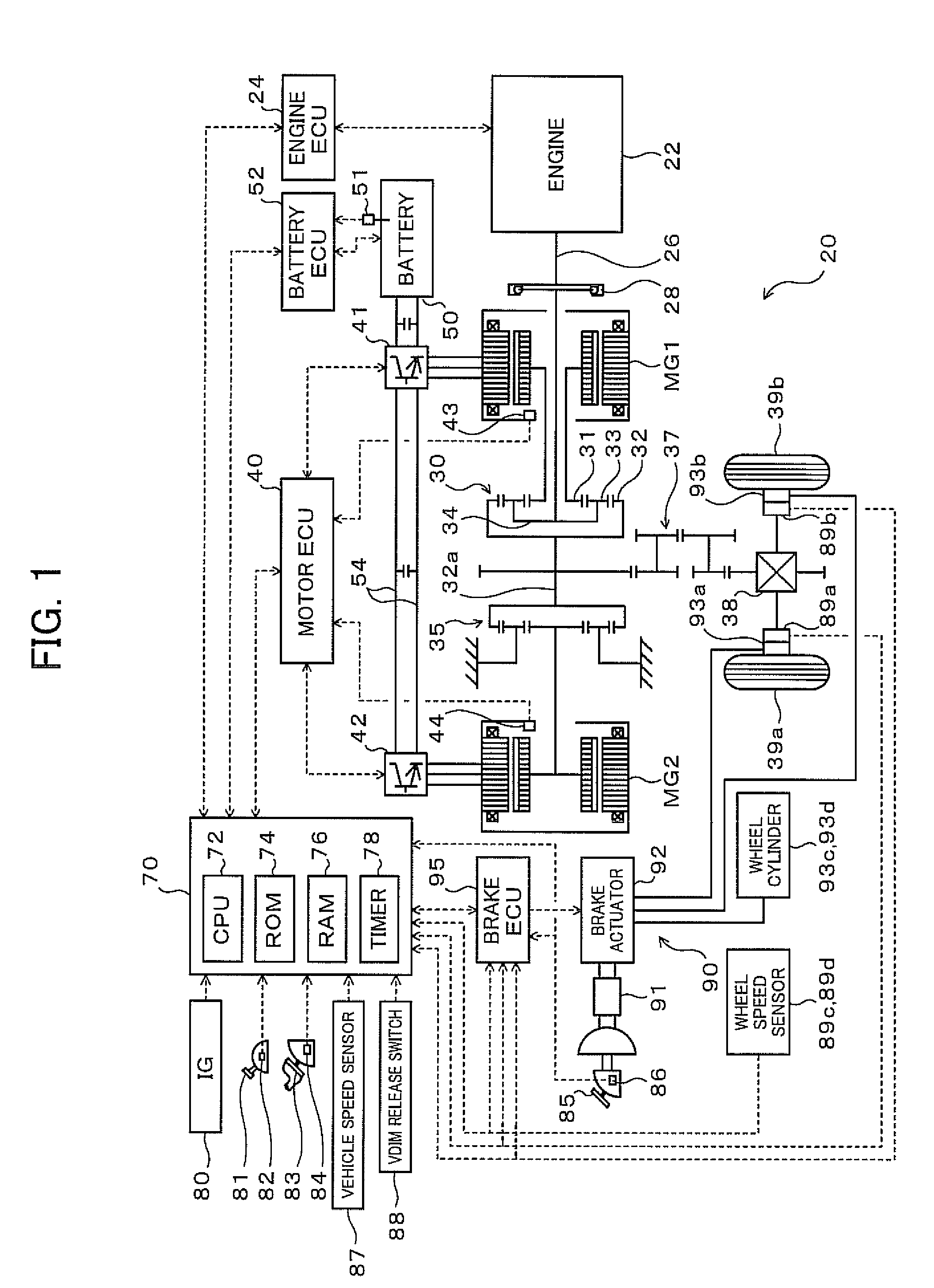
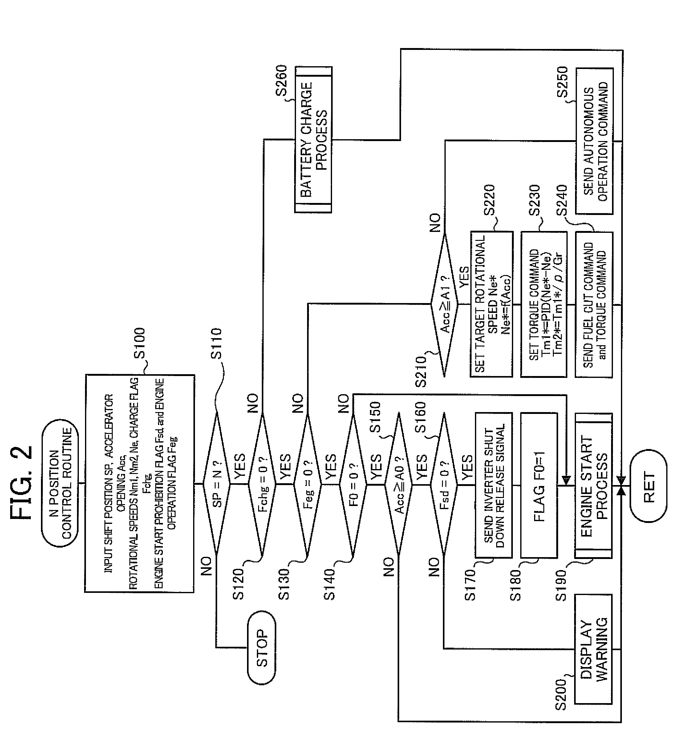
[0046]FIG. 1 is a schematic block diagram of a hybrid vehicle 20 according an embodiment of the present invention. The hybrid vehicle 20 of the illustrated configuration includes an engine 22, a three shaft-type power distribution integration mechanism 30 connected via a damper 28 to a crankshaft (engine shaft) 26 of the engine 22, a motor MG1 connected to the power distribution integration mechanism 30 and designed to have power generation capability, a reduction gear 35 attached to a ring gear shaft 32a as an axle connected to the power distribution integration mechanism 30, a motor MG2 connected to the ring gear shaft 32a via the reduction gear 35, an electrically controlled hydraulic brake unit 90 (hereinafter referred to as “brake unit”) capable of providing a frictional braking force, and a hybrid electronic control unit 70 (hereinafter referred to as “hybrid ECU”) c...


PUM


Abstract

When an accelerator opening Acc is equal to or more than a threshold value A2 upon a shift from a N position to a D position, a target torque T* is set to gradually change in comparison with when the accelerator opening Acc is less than the threshold value A2 based on a torque demand Trq corresponding to the accelerator opening Acc and a time constant T or a gradual change restriction until a satisfaction of a release condition. An Engine 22, motors MG1 and MG2 are controlled so as to ensure a driving torque equivalent to the target torque T*.

Description

[0001]The disclosure of Japanese Patent Application No. 2008-180915 filed Jul. 11, 2008 including specification, drawings and claims is incorporated herein by reference in its entirety.BACKGROUND OF THE INVENTION[0002]1. Field of the Invention[0003]The present invention relates to a hybrid vehicle and a control method thereof.[0004]2. Description of the Prior Art[0005]Conventionally, there is known a hybrid vehicle that includes an internal combustion engine connected to an axle via a planetary gear mechanism, a generator connected to the planetary gear mechanism, and a motor connected to the axle via a transmission having two hydraulic brakes (for example, refer to Japanese patent laid-open publication No. 2005-306238). In the hybrid vehicle, when a start of the internal combustion engine is instructed while a shift position is set to a neutral position (N range) and inverters for the generator and the motor are shut down, the start of the internal combustion engine is prohibited u...

Claims


Application Information

Patent Timeline
Patent Type & Authority Applications(United States)
IPC IPC(8): B60W10/04B60W20/00B60K6/445B60K6/448B60K6/52B60K6/547B60L50/16B60W10/06B60W10/08B60W10/10B60W10/11B60W30/02B60W30/19F02D29/00F02D29/02
CPCB60K1/02Y02T10/48B60K6/445B60K6/448B60K6/52B60K6/547B60L2240/421B60L2240/423B60L2240/486B60W10/06B60W10/08B60W10/115B60W20/00B60W30/188B60W2510/081B60W2520/10B60W2520/28B60W2540/10B60W2540/12B60W2540/16B60W2710/0644B60W2710/0666B60W2710/083Y02T10/6239Y02T10/6243Y02T10/6265Y02T10/6286Y02T10/642B60K6/365Y02T10/40Y02T10/62Y02T10/64B60W2050/143B60W2050/146B60W30/18027B60W30/02
Inventor ISHIKAWA, NAOKI
Owner TOYOTA JIDOSHA KK
Why Eureka
Try Eureka