Air separation plant, method for obtaining a product containing argon, and method for creating an air separation plant

a separation plant and air separation technology, applied in the direction of lighting and heating equipment, refrigeration and liquid separation, solidification, etc., can solve the problem that the corresponding air separation plant is scarcely prefabricable any longer

Active Publication Date: 2015-12-24
LINDE AG
View PDF5 Cites 3 Cited by
  • Summary
  • Abstract
  • Description
  • Claims
  • Application Information

AI Technical Summary

Benefits of technology

[0013]According to the invention, an air separation plant is proposed which is designed tor obtaining an argon-containing product by low-temperature separation of compressed and cooled feed air. The air separation plant has a high-pressure column, a low-pressure column which is constructed in a multi-part manner and a crude argon column which is constructed in a multi-part manner. The low-pressure column which is constructed in a multi-part manner and the crude argon column which is constructed in a multi-part manner each have at least one foot section and a top section arranged spatially separate therefrom. In particular, the low-pressure column constructed in a multi-part manner and the crude argon column constructed in a multi-part manner are each constructed in a two-part manner.
[0014]The air separation plant operates on the basis of the principles explained at the outset, wherein an argon-enriched stream can be withdrawn from the low-pressure column of the air separation plant.
[0015]The “argon-containing product” can be for example, liquid argon (LAR), gaseous argon (GAR, optionally obtained by what is termed internal compression) or what is termed fake argon (impure argon which is added to a residual gas gaseous in the cold state). The invention will be explained hereinafter predominantly by the example of liquid pure argon (LAR), which is termed “argon product” for short.
[0016]A column “constructed in a two-part manner” is constructed, as mentioned, in such a manner that the two sections (top section and foot section) are arrangeable spatially separate from one another. Known air separation plants can have, for example, column systems for nitrogen-oxygen separation in which the high-pressure column and the low-pressure column are arranged separate from one another and are heat-exchangingly connected via an overhead condenser. Such column systems are “constructed in a two-part manner”. The expression “constructed in a two-part manner” therefore delimits corresponding configurations from structural units in which components are permanently connected to one another and are not arrangeable separate from one another.
[0017]“Foot section” and “top section” each denote the sections of columns constructed in a two-part manner which correspond in function thereof, in particular with respect to the fractions or streams arising there, to the lowest or topmost sections of customary columns constructed in a one-part manner. A foot section has, for example, a sump container; a top section has, for example, an overhead condenser. The top section is therefore the part of the columns which is connected to a corresponding condenser, and in which a return is applied to the corresponding columns. In a low-pressure column constructed in a one-part manner of known air separation plants, in the sump, an oxygen-rich liquid fraction is obtained which can be taken off as an oxygen product. This also proceeds thereby in a sump of a foot section of a low-pressure column constructed in a two-part manner. At the top of a low-pressure column constructed In a one-part manner of known air separation plants, correspondingly a gaseous nitrogen product can be taken off, and the same applies to the upper part of a top section of a low-pressure column constructed in a two-part manner. At the top of a crude argon column constructed in a one-part manner—and correspondingly at the upper part of a top section of a crude argon column constructed in a two-part manner—a crude argon stream is taken off and transferred to a pure argon column, from the sump of a crude argon column constructed in a one-part manner-and correspondingly from the sump of a foot section of a crude argon column constructed in a two-part manner—the sump product that arises is fed back to the low-pressure column.
[0018]If a low-pressure and / or crude argon column, constructed in a “multi-part” manner, has more than two parts, in addition intermediate sections between toot section and top section are provided. The individual sections (foot, top and optionally intermediate sections) are connected to one another by means of lines and optionally pumps, in order in this manner to provide an operation as also proceeds in the case of a respectively one-piece column.

Problems solved by technology

When air separation plants are being generated for argon production, problems result on account of the dimensions of the columns used, in particular of the crude argon column.
Corresponding air separation plants are scarcely prefabricatable any longer, because the respective component groups can generally no longer be transported over relatively long sections.
This means that they have to be erected at the respective target site, This is disadvantageous for various reasons, inter alia, because corresponding staff at the target site are either not available or expensive.

Method used


Image

  • Air separation plant, method for obtaining a product containing argon, and method for creating an air separation plant
  • Air separation plant, method for obtaining a product containing argon, and method for creating an air separation plant
  • Air separation plant, method for obtaining a product containing argon, and method for creating an air separation plant

Examples


Embodiment Construction

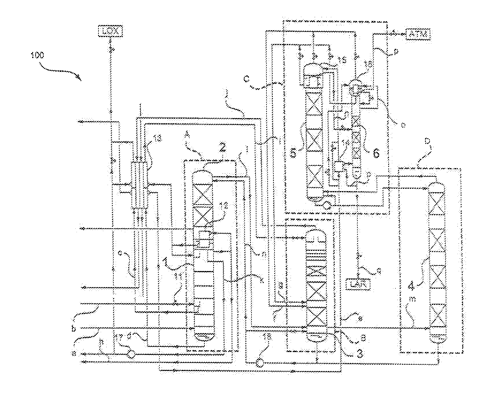
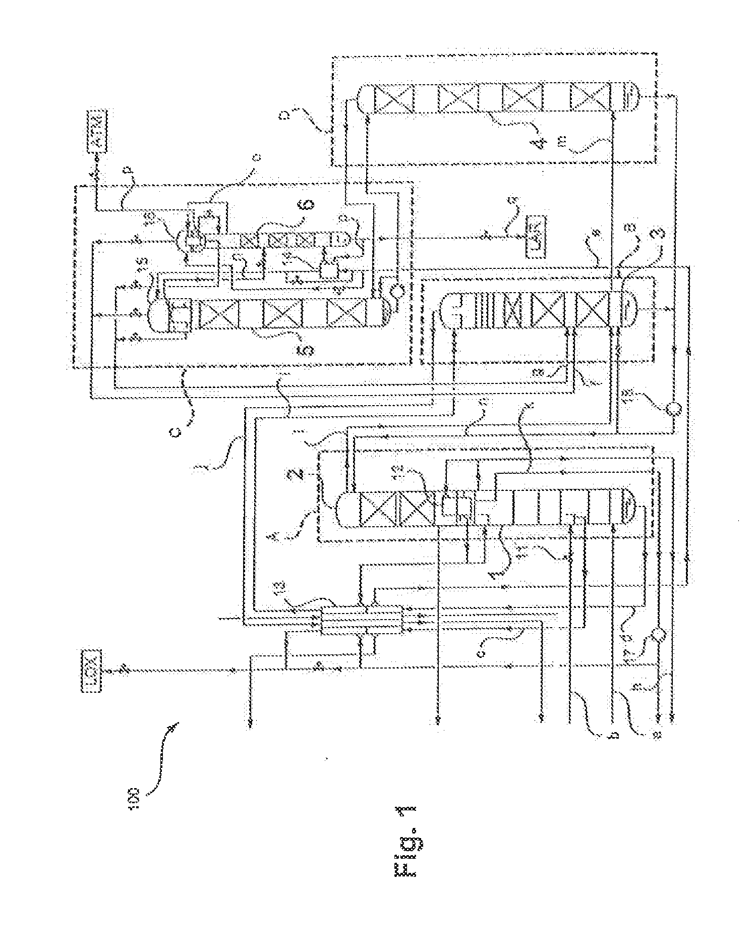
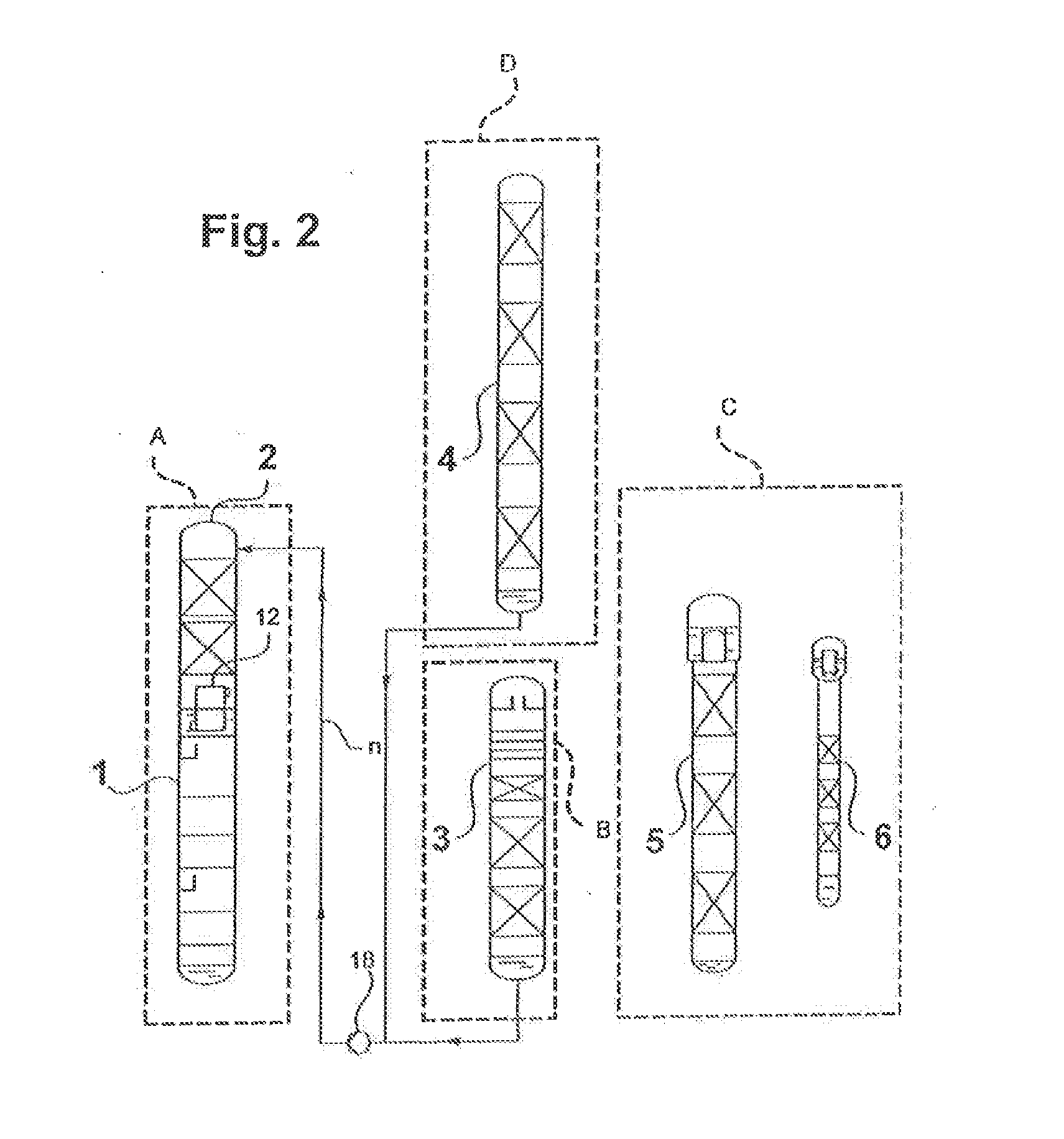
[0040]In the figures, elements corresponding to one another are given identical reference signs. Repeated explanation of the same is dispensed with.

[0041]It is stressed explicitly that the arrangement of the components of the air separation plants shown in FIGS. 1 and 2 is only by way of example and that, in particular, the dimensions of the components shown there, in particular the columns, are not correct to scale. As mentioned, the crude argon column of a corresponding air separation plant generally has the greatest height, which is not reproduced correct to scale in the drawing. Also plants having what are termed dummy columns are known, from which only argon is taken off in order to achieve an energy advantage. Such columns are markedly lower, that is to say also lower than the other columns.

[0042]FIG. 1 shows schematically an air separation plant according to the invention for obtaining an argon product and which is denoted overall with 100. The air separation plant, as separa...


PUM


Abstract

An air separation plant for obtaining product containing argon by low temperature separation of compressed, cooled feed air. The air separation plant comprises a high-pressure column, a multi-part low-pressure column having a base segment and a head segment and a multi-part crude argon column having a base segment and a head segment. An oxygen-enriched flow is obtained from part of the feed air in the high pressure column, an argon-enriched flow is obtained from part of the oxygen-enriched flow in the low-pressure column, and an argon-rich flow is obtained from part of the argon-enriched flow in the crude argon column. Liquid flow is transferred from a lower region of the head segment of the low-pressure column and from a lower region of the base segment of the crude argon column into an upper region of the base segment of the low-pressure column.

Description

[0001]The present invention relates to an air separation plant, a method for obtaining an argon product by low-temperature separation of air, and a method for generating a corresponding air separation plant.PRIOR ART[0002]Obtaining argon by low-temperature separation of air is described, for example, in the article “Noble Gases” in Ullmann's Encyclopedia of Industrial Chemistry (doi: 10.1002 / 14356007.a17—485). As explained there, for example in FIG. 18, argon can be obtained in customary air separation plants having known twin-column systems for nitrogen-oxygen separation and an additional argon production unit.[0003]In such twin-column systems, argon accumulates in the region of what is termed the argon transition in the low-pressure column (also termed argon bubble) and there reaches concentrations in the gas phase of up to 15%. In practical use, an argon-enriched stream is taken off from the low-pressure column somewhat below this argon maximum, in order that said stream has a lo...

Claims


Application Information

Patent Timeline
Patent Type & Authority Applications(United States)
IPC IPC(8): F25J3/02F25J3/04
CPCF25J3/0285F25J3/04424F25J3/04048F25J3/04872F25J3/04878F25J3/0489F25J3/0409F25J3/04412F25J3/04678F25J3/04703F25J3/04727F25J2235/02F25J2235/52F25J2235/58F25J3/04624F25J3/04666F25J3/04654
Inventor LOCHNER, STEFAN
Owner LINDE AG
Why Eureka
Try Eureka